
- Rochester Quadrajet Rebuild
- Quadrajet Needle & Seat Replacement
- Quadrajet Troubleshooting
- Quadrajet Jet Sizes
- Quadrajet Choke Circuit
- Quadrajet Secondary Circuit
- Quadrajet Accelerator Pump
- Quadrajet Idle Circuit
- Quadrajet Flooding
- Quadrajet Float Circuit
- How the Quadrajet Metering Rods Work
- Screws Rochester Quadrajet
- Thermostatic Idle Vent
- Rochester Quadrajet Exploded Views and Images
- Quadrajet Adjustments
- Common Rochester Quadrajet Carburetor Problems and How to Fix Them
- Electronic Quadrajet Carburetor Diagram
- Quadrajet Throttle Position Sensor
- Quadrajet Electronic Carburetor Rebuild
- Quadrajet Throttle Positioning Sensor
- Quadrajet Primary Enrichment assembly
- Does My Quadrajet Need a Primary Pull-off?

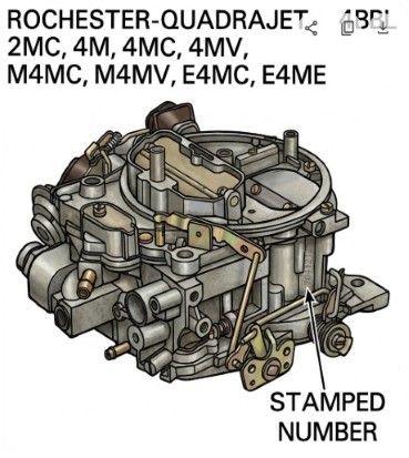
IDENTIFICATION
Buy Your Quadrajet Parts Here.
Cleaning - Soak the parts in a bucket of carburetor cleaner (any parts store type), overnight. Flush with hot water. Run thin wire down all of the small passage ways. Ethanol will leave deposits that cleaner will not remove.
Polish the accelerator pump well so that the pump cup glides smoothly. Any binding will cause the cup to fold over and tear.
Free Rochester Quadrajet Manuals
Rochester Quadrajet Carburetor Manual
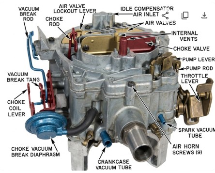
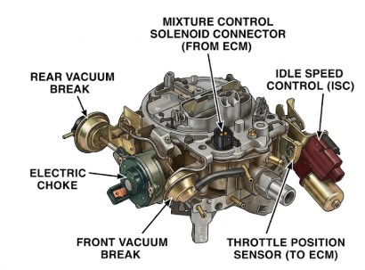
E4MC, E4ME Adjustment Procedures
Metering Rod Sizes
Primary Jet Sizes
I have a Rochester Quadrajet Marine Carburetor #17059286. It appeared to be flooding at idle and the fuel was leaking excessively from the throttle body linkages (on both left & right side). I assumed the carb needed to be rebuilt and the leaking was normal (from a drain in the carb) when flooded. I rebuilt it using a kit I ordered from you. I reinstalled the carb and I'm having the same issue of fuel leaking from the throttle body linkages. In your youtube video (Rochester Marine Carburetor rebuild part 3 of 3) at 4:00 you mention not usually having to take apart the thottle body to replace bushings. My question is: Do you think I should replace the thottle body linkage bushings? And if so, do you carry the kit? I think this is what I need to do. However, I read a post online that said the fuel at the thottlebody should already be atomized, and should therefore not leak out the linkage,and that would indicate that the carb is flooding due to the float not being adjusted properly. I set the float to 3/16 like the instructions stated. Any thoughts on this would be greatly appreciated.
Your problem is not bushings. The carburetor is simply puking out too much fuel. The bushings are replaced only if you have excessive free play in the throttle shaft. Flooding fuel will leak out anywhere it can and onto the throttle valves and out the shaft is the 1st place fuel likes to go.
Too much fuel boils down to getting too much in the float bowl. Did you test the (brass) float for leaks? Immerse the float in hot water and if there are any leaks, it will bubble. If you have a Nitrophyl float (black plastic kind of thing), replace it. They absorb fuel over time.
Did you put the fiber washer where the seat screws into the float bowl.
Many times after rebuilding a carburetor and after re-starting the engine, crud from the tank and the fuel lines will rush up to the carburetor and into the needle & seat causing it to stick open. Take the carburetor apart and wash out the needle & seat and try again.
Manually move the float up and down and watch for any kind of rubbing, or catching. Also watch the needle to make sure it is move straight up and down and not getting caught up.
Too much fuel pump pressure could be holding the needle open. Any chance you replaced the pump with a new one? New pumps are always suspect because they come from China and they don't seem to care about specifications very much yet.
These are just a few ideas, but bottom line is that too much fuel is getting into the float bowl.

Some applications from 1967 to the late 1970s used a hot idle compensator that was located in the rear of the float bowl (our feature car had the place in the casting, but was not equipped with one). It was used to compensate for an overly rich mixture from excessive fuel vaporization in high-heat conditions. A bimetallic spring that responded to temperature would then open a port and introduce fresh air into the idle circuit to lean the air/fuel ratio.
