
Rochester Varajet Rebuilding Steps
Rebuilding a Rochester Varajet carburetor (such as the 2SE or electronic E2SE models) is a precise job. Because the Varajet features a unique mix of fixed and variable stages, keeping your work organized and completely clean is vital to preventing warped castings or vacuum leaks.
The complete, step-by-step rebuilding procedures are detailed below.
Tools & Prep Work
Tools needed: A standard carburetor rebuild kit (gaskets, needle/seat, accelerator pump), from Mike's Carburetor Parts a flathead screwdriver that snugly fits the jets, a Philips screwdriver, a needle-nose pliers, a clean container for carburetor dipping solvent, and compressed air.
Safety First: Work in a well-ventilated space. Carburetor cleaner is highly flammable and harsh on the skin/eyes; wear safety goggles and nitrile gloves.
1. Disassembly
To avoid bending internal components, follow a strict top-down breakdown.
Step A: The Air Horn (Top Section)
Disconnect the Linkages: Disconnect the choke rods, vacuum break lines, and the fast idle cam rod at one end only.
Remove the Mixture Control Solenoid (E2SE only): If you are working on an electronic feedback model, carefully unscrew and remove the electrical solenoid from the top.
Unscrew the Air Horn: Remove the screws in the exact reverse order of the tightening sequence to prevent warping the metal. Note that the screws have different lengths:
Screws 2 & 3 are longer and hold down the vent and screen assembly.
Screws 5 & 6 are short and located on the fuel inlet side.
Lift Vertically: Lift the air horn straight up. Do not force or pry it, as you could easily bend the tubes extending out from the bottom.
Step B: The Float Bowl & Accelerator Pump
Remove the Accelerator Pump: The accelerator pump plunger has a spring underneath it. Carefully lift it out so it doesn’t shoot out. Be absolutely ready to catch the small check ball located underneath the pump spring!
Remove the Float: Slide out the float pivot pin and lift the float out. The float needle will come out with it, hooked by its small retaining clip.
Remove the Fuel Inlet & Seat: Unscrew the fuel filter housing at the inlet, pull out the filter and spring, and use a wide flathead screwdriver to remove the needle seat from the bottom of the bowl.
Step C: Throttle Body Separation
Unbolt the primary throttle body from the main float bowl casting if your kit includes a base gasket.
Note on Factory Plugs: If you need to access the recessed idle mixture screw, you will have to gently punch out the factory-installed hardened steel tamper-proof plug.
2. Cleaning & Inspection
Warning: Do not soak any rubber parts, plastic components, plungers with leather seals, or electronic solenoids in the chemical dipping solvent. We use Chem Dip bought at most part stores.
The Soak: Submerge only the bare metal castings (air horn, bowl, base) into a carburetor cleaning dip for 15–30 minutes.
Clear the Passages: Rinse the parts thoroughly with water or spray carb cleaner, then use compressed air to blow out all internal channels and jets.
Never use a metal wire or drill bits to clear out the jets; this will gouge the brass and permanently ruin the fuel metering calibration.
Inspect for Wear: Check the throttle shafts for excessive wiggle. If the throttle shafts have play, they will introduce a vacuum leak that will prevent a stable idle.
3. Reassembly & Adjustments
Always use the fresh gaskets provided in your rebuild kit. Match them exactly to the old ones to ensure all vacuum/fuel passages match up perfectly.
Step A: Setting the Float Level
Install the new needle seat into the float bowl.
Attach the new needle and its clip back onto the float arm. The clip must hook over the edge of the flat on the float arm in the direction opposite the float pontoon.
Adjust the Level: Install the float and hinge pin. Hold the float hinge pin firmly down and lightly push the float arm down against the needle. Do not force it into the seat.
Measure from the top edge of the casting to the top of the float (at the point furthest away from the hinge). Carefully bend the metal float arm to match your kit's exact specification sheet.
Step B: Reassembling the Pump & Air Horn
Drop the pump check ball back into its well, place the spring over it, and insert the accelerator pump plunger (lube the seal slightly with light oil).
Lay the new air horn gasket smoothly over the float bowl.
Carefully lower the air horn straight down, ensuring the tubes smoothly guide into their respective channels.
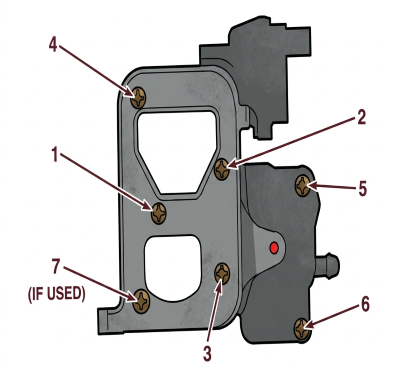
4. Air Horn Screw Tightening Sequence
To guarantee a uniform gasket seal and stop vacuum or fuel leaks, tighten the screws down evenly in a multi-stage process following this pattern:
5. Bench Adjustments
Before putting the unit back on the vehicle, reinstall all linkages and check the choke settings. Use the instructions and cardboard templates provided in your specific rebuild kit to check:
Choke Coil Lever Adjustment
Fast Idle Cam Clearance
Vacuum Break (Choke Pull-Off) Angle (Best measured using a magnetic angle gauge on the choke valve).
Once the carburetor is bolted back onto the engine intake manifold, you can perform your final hot-idle and idle-mixture adjustments.

