HOW IT WORKS
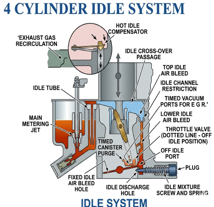
The model 2SE carburetor has an idle system in the primary stage to supply the correct air/fuel mixture to the engine during idle and off-idle operation. The idle system is used during this period because air flow through the carburetor is not great enough to obtain efficient metering from the main discharge nozzle.
The idle system consists of an idle fuel well, a fuel pick up tube, idle corss-over passage in the top of the float bowl, top idle air bleed, down channel with restriction, lower idle air bleed, off-idle discharge port, idle mixture screw orifice, and idle mixture screw. Also, a hot idle compensator may be included int he idle system.
Fuel flows from the float chamber down through the main metering jet into the main fuel well. It is picked up in the main well by the idle tube. The fuel is metered at the lower tip of the submerged idle tube and passes up through the tube. Then the fuel crosses over through the bowl passage to the idle down channel, past the top air bleed, and continues down through the calibrated idle channel restriction past the lower idle air bleed and off-idle discharge port where it is further mixed with the air. The air/fuel mixture moves down to the adjustable idle mixture screw discharge hole where it enters the carburetor bore and blends with the air passing the slightly open throttle valve.
As the primary throttle valve opens, it passes byt the slotted off-idle discharge port, gradually exposing it to high engine manifold vacuum. The additional mixture, added from the off-idle port, mixes with the increasing air flow past the opening throttle valve to maintaint he required air/fuel mixture of the engine.
The exhaust gas recirculation (EGR) valve is operated by a vacuum signal taken from the carburetor. A vacuum supply tube connects to the vacuum ports located just above the throttle valve in the throttle body bore. The ports create a vacuum signal for EGR valve operation.
The evaporation emissions vapor canister is purged by an off-idle (times) purge port located in the carburetor throttle body. The off-idle purge port connects to a tube located in the throttle body casting which goes directly to the canister through a hose. The off-idle purge port purges the canister during off-idle, part throttle, and power operation.
The idle mixture needle is recessed in the throttle body casting and sealed with a hardened steel plug to discourage tampering with the factory adjusted mixture setting in the field which could upset exhaust emissions. The plug must not be removed and idle mixture screw re-adjusted unless required during major carburetor overhaul or throttle body replacement in which case special service procedures must be followed carefully.
6 CYLINDER IDLE SYSTEM
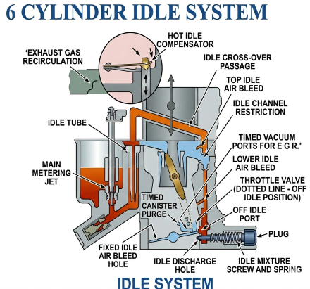
The idle system on 2SE models for the 6 cylinder light duty truck engine operates similar to that described above for 4 cylinder models except fuel is tracked through an idle cross-over passage located in the air horn (vs float bowl).
A hot idle compensator (when used) is located in the air horn casting and consists of a thermostatically controlled valve, a heat-sensitive bi-metal strip, a valve holder and bracket, and two screws that hold the assembly in place on the air horn. The opening and closing of the hot idle compensator valve is controlled by the bi-metal strip which senses carburetor air inlet temperature. At a certain pre-determined temperature, the bi-metal strip bends and opens the valve to allow additional air to by-pass the throttle valves at idle and enter the intake manifold. This additional air off-sets the enrichening effects of fuel vapors in the intake manifold to prevent rough idle and stalling during periods of hot engine operation.
There are no purge ports located in the throttle body for purging of the vapor canister on 6 cylinder 2SE models; however, a vacuum tube in the float bowl is used as the full vacuum source to operate the vapor vent valve located in the vapor canister.
Similar to the 4 cylinder 2SE models, the idle mixture needle is recessed in the throttle body casting and sealed with a hardened steel plug to discourage tampering with the factory adjusted mixture setting in the field which could upset exhaust emissions. The plug must not be removed and idle mixture screw re-adjusted unless required during major carburetor overhaul or throttle body replacement in which case special service procedures must be followed carefully.
Common Varajet idle mixture screws and spring are available on our website:


ADJUSTMENTS
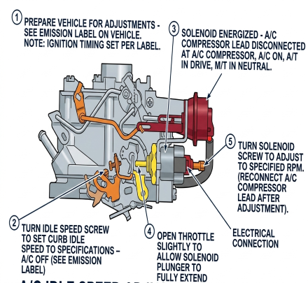
A/C IDLE SPEED SOLENOID ADJUSTMENT (4 CYLINDER)
- Prepare vehicle for adjustments - see emission label on vehicle
- NOTE: Ignition timing set per label
- Turn idle speed screw to set curb idle speed to specifications - A/C off (see emission label)
- Solenoid energized - A/C compressor lead disconnected at A/C compressor, A/C on, A/T in drive, M/T in neutral
- Open throttle slightly to allow solenoid plunger to fully extend
- Turn solenoid screw to adjust to specified RPM. Reconnect A/C compressor lead after adjustment
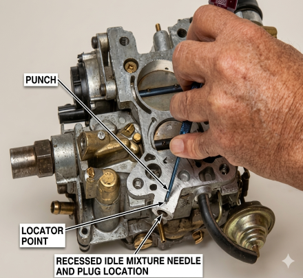
IDLE MIXTURE NEEDLE REMOVAL AND ADJUSTMENT
- Remove idle mixture needle and plug as follows
- Place a punch in the locator point in the throttle body beneath the idle mixture needle plug (manifold side)
- Holding the punch vertical, drive punch through the locator until hardened steel plug shatters
- Holding punch at a 45* angle, breakout throttle body casting to gain access to the mixture needle plug
- NOTE: hardened plug will shatter rather than remaining intact. It is not necessary to remove the plug completely; instead, remove loose pieces to allow use of deep socket
- Using deep socket, remove idle needle, washer, and spring from throttle body
- Install idle mixture needle, washer, and spring using deep socket. Lightly seat needle and then back out specified number of turns as a preliminary idle mixture adjustment. Final idle mixture adjustment must be made on-car using factory recommended procedures