
Marvel Schebler Carburetor Adjustments – Step-by-Step Tuning Guide
Marvel Schebler carburetors are known for their durability and simplicity, making them a popular choice for tractors, stationary engines, and vintage equipment. However, to get the best performance and fuel economy, proper adjustment is essential. Whether you've just rebuilt your carburetor or you're trying to fix a poor idle, follow this guide to adjust your Marvel Schebler the right way.
Tools You’ll Need:
Flathead screwdriver
Tachometer (optional, but helpful)
Carburetor cleaner (for leak testing)
Vacuum gauge (optional)
Safety gear (gloves, eyewear)
Step-by-Step Marvel Schebler Adjustment Procedure
1. Warm Up the Engine
Start the engine and allow it to reach full operating temperature. A cold engine will give false readings during adjustment.
2. Set the Idle Speed
Locate the idle speed screw, typically on the throttle body. Set the idle to the manufacturer’s specification, often around 400–600 RPM depending on your application.
Turn screw clockwise to increase idle speed.
Turn screw counterclockwise to decrease it.
Note: Make sure the choke is fully open before setting idle.
3. Adjust the Idle Mixture Screw
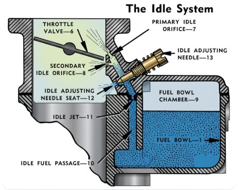
This screw controls the fuel/air mixture at idle and low throttle positions. Most Marvel Schebler carbs have one idle mixture screw, though some have two.
Turn the screw in (clockwise) to lean the mixture.
Turn the screw out (counterclockwise) to richen the mixture.
Adjustment steps:
Gently turn the screw in until it just seats. Do not overtighten.
Back the screw out 1½ turns as a baseline.
Slowly turn in ¼ turn at a time until engine stumbles.
Then back out slowly until RPM peaks and smooths out.
Repeat this with the idle speed screw if needed to maintain target RPM.
4. Check Throttle Shaft and Linkage
Make sure the throttle shaft is not excessively worn and that the return spring brings the throttle back to idle properly. A worn shaft may cause vacuum leaks that prevent proper tuning. While running, spray carb cleaner around the throttle shaft. An RPM change indicates too much play in the shaft. For the type that uses 0 rings, replace them. For the type that doesn't use any seals re-bush the shaft ends.
5. Adjust the Float (During Rebuild or If Fuel Starvation Suspected)
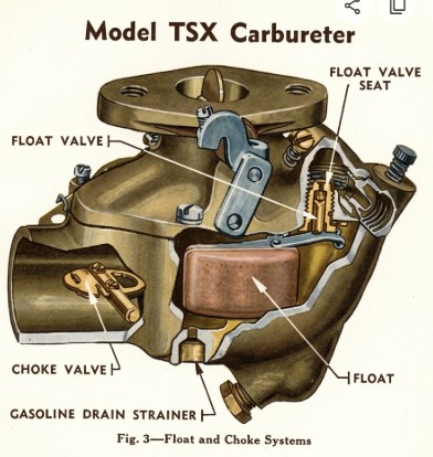
The float setting controls fuel level in the bowl. A float that’s too high causes flooding; too low causes starvation.
Refer to your specific Marvel Schebler model’s manual for float height specs.
Adjust the tang on the float to raise or lower fuel level.
6. Governor Linkage (If Equipped)
On tractors with a mechanical governor, be sure the governor-to-carburetor linkage is free of slop and adjusted to spec. An out-of-adjustment governor can override your idle settings and cause surging

Troubleshooting After Adjustment
Surging at idle or light throttle: Lean idle, vacuum leak, or dirty idle circuit.
Black smoke: Mixture too rich.
Engine stalls under load: Clogged main jet, low float, or power circuit not working.
No RPM change when adjusting idle mixture: Idle circuit plugged or idle RPM set too high (off the idle system).
Pro Tip: Cleanliness Is Everything
Many Marvel Schebler tuning issues trace back to partially blocked passages or ethanol residue. Always ensure the idle, transition, and main fuel circuits are spotless before final adjustment.
Final Thoughts
With just a few basic tools and some patience, you can dial in a Marvel Schebler carburetor for smooth idling, crisp throttle response, and reliable power under load. Regular maintenance and careful adjustments will keep your equipment running like it should.
Marvel-Schebler Carburetor Float Settings
2.2 - 3.2"
From the bottom of the nozzle boss to the nearest surface of the float.
1/4"
From the bowl gasket to the nearest surface of the float.
1/2"
From the bowl gasket to the nearest surface of the float.
3/4"
From the bowl gasket seat in casting to the bottom of float.
From the gasket to the top of the float.
From the top of the float to the gasket.
From the top of the float to the gasket.
From the bowl cover face to the bottom of the float.
1/8"
From the top of float to flange gasket.
From upper bowl gasket to bottom of float.
7/8"
From the gasket to the bottom of the float.
1/4"
From the gasket to the nearest surface of the float.
1/4"
From the gasket to the nearest surface of the float.
From the face of the flange to the bottom of the float.
From the gasket to the end of float furthest from hinge pin.
From the nozzle boss to the end of the float furthest from hinge pin.
From the gasket flange face to the bottom of the float.
