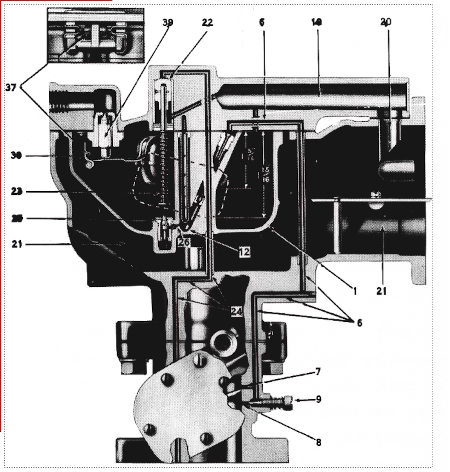
IDLE SYSTEM
The fuel from the carburetor float bowl (1) passes through the main metering jet (2) into the idle tube (3) as shown in Figure A, Air is introduced into the fuel stream by idle air bleed (4) and passage (5), Figure A.FIG A

This fuel and air mixture then travels through the idle passage (6) to the idle discharge holes (7)and (8) as shown 1n Figure E.
When the Engine is set to idle at a speed of approximately 400 R.P.M. the mixture is discharged out of lower hole (8) only, Figure E· As the throttle is opened and the speed increases, the upper hole (7), Figure E, starts discharging, in addition to the lower hole at about 600 R.P.M.
FIG B
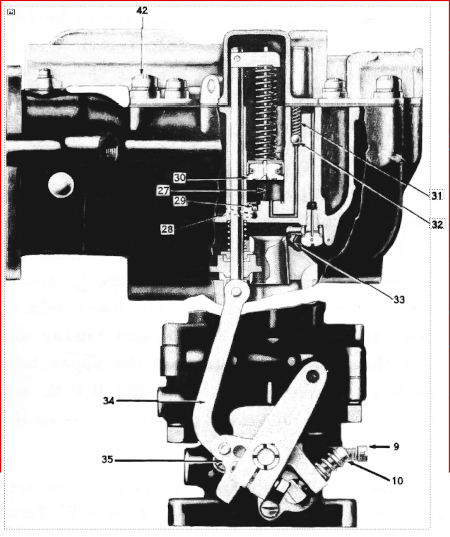
The action and timing are such that the discharge from the upper hole reaches its maximum at about 800 R.P.M. and then gradually becomes less effective as the main nozzle commences to flow.
FIG C
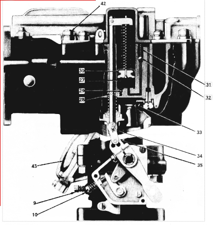
The lower discharge hole is provided with an idle adjusting needle (9), Figure E-Turning this needle out (to the left) gives a richer mixture and turning in (to the right) a leaner mixture. The idle speed is regulated by the screw (10) as shown in Figures B & C.
FIG E