How To Adjust Holley 4360 Float Level?
Adjusting the float on a Holley 4360 (their compact, spread-bore 4-barrel model) is completely different from a standard Holley 4150 or 4160. Because the 4360 uses a single, centrally located fuel bowl built right into the main body, you cannot adjust the floats externally while the engine is running.
The adjustment must be made dry, with the air horn (top casting) removed and inverted.
Technical Specifications
-
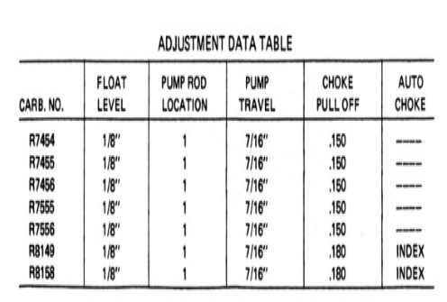
Float Level Setting: 11/32 inch (Standard factory specification)
-
Measurement Point: Measured from the surface of the inverted air horn gasket to the top of the float pontoon at its highest point.
Adjustment Procedure
Disconnect the choke and throttle linkages. Remove the air horn screws and carefully lift the air horn straight up from the main body to prevent damaging the continuous dual-pontoon float (which wraps around the central bore area).
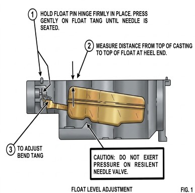
Turn the air horn completely upside down so that the weight of the float assembly rests naturally on the vitreous (rubber-tipped) needle and seat. Ensure the tiny needle pull-clip is correctly positioned and not binding.
Place an 11/32-inch drill bit or a dedicated T-scale gauge across the surface of the air horn gasket. Measure the distance between the gasket surface and the top edge of the float pontoon at its outer end. Both pontoons must sit level with each other.
If adjustment is necessary, use needle-nose pliers to gently bend the horizontal tang located at the rear center of the float arm assembly.
To lower the fuel level in the bowl, bend the tang toward the needle seat.
To raise the fuel level, bend the tang away from the needle seat.
Critical Step Safety: Never press down on the float pontoons while bending the tang. The leverage will crush the rubber tip of the needle or score the brass seat, causing the carburetor to bleed fuel and flood out once reassembled. Always support the float arm structure directly while making adjustments.
Turn the air horn right-side up to check the free-hanging drop. The float should drop down smoothly without binding against the sides of the bowl area, allowing full fuel flow volume when the bowl is empty.
Reassembly Tip
When dropping the air horn back onto the main body, ensure the float pontoons clear the internal main metering wells and baffle plates without scraping. Secure the top screws evenly in a cross-pattern to prevent warping the gasket surface.
How Does The Float System Work in a Holley 4360
Unlike standard Holley four-barrels that feature two separate fuel bowls bolted to the front and rear, the Holley 4360 uses a centralized fuel bowl design. It is built directly into the center of the main body casting, completely surrounding the venturis.
Because of this unique layout, it relies on a single, continuous dual-pontoon float shaped like a horseshoe. Here is a breakdown of how the components work together to manage fuel delivery.
1. The Fuel Inlet and Needle Seat
Fuel enters the carburetor through the main fuel inlet fitting on the air horn (the top casting). Directly inside this inlet sits the needle and seat assembly.
-
The seat is a stationary brass orifice.
-
The needle is a small, movable plunger (typically with a soft, fuel-resistant viton tip) that moves up and down inside the seat to block or allow fuel flow.
2. The Horseshoe Float Mechanism
The 4360 features a unique, lightweight dual-pontoon float assembly made of nitrophyl (a closed-cell cellular plastic) or brass. The two pontoons hang down into the central fuel reservoir on either side of the primary bores.
-
Both pontoons are connected by a rigid, stamped metal float arm.
-
This arm pivots on a single hinge pin attached to the underside of the air horn casting.
-
At the center of the pivot arm is a small metal tab called the tang, which rides directly against the bottom of the fuel needle.
3. The Buoyancy Cycle (How it regulates fuel)
The system operates as a continuous, self-correcting balance scale based entirely on the fuel level inside the bowl:
-
When the engine is running and consuming fuel: The fuel level inside the centralized bowl drops. As the liquid level falls, gravity causes the heavy float pontoons to sink downward. The pivoting arm pulls away from the needle, allowing pump pressure to push the needle out of its seat. Fuel rushes into the bowl to replenish the supply.
-
As the bowl fills back up: The rising fuel lifts the buoyant pontoons upward. As the float assembly pivots up, the metal tang presses firmly against the bottom of the needle, pushing it upward into the brass seat. Once the fuel reaches the calibrated height (11/32"), the needle completely seals the orifice, stopping the incoming fuel.
Why This Design Matters
The centralized, horseshoe float system was engineered specifically to handle vehicle maneuvers and fuel slosh.
In traditional dual-bowl carburetors, hard braking, sharp cornering, or steep inclines cause fuel to slosh to one side of the bowl, either starving the jets or flooding the vents. Because the 4360’s fuel reservoir wraps completely around the center of the carburetor, the fuel mass stays centered relative to the main metering circuits. When the vehicle corners hard, the fuel level may rise on one pontoon but it drops on the other, averaging out the forces so the needle and seat maintain a highly stable, consistent fuel level.