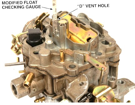
- Remove air horn following normal service procedures
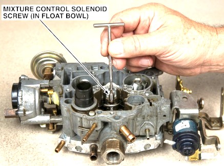
- Using tool J-28696 or equivalent, turn mixtue control solenoid screw in float bowl clockwise until bottomed lightly COUNTING NUMBER OF TURNS. If not within 1 1/2 - 2 1/2 turns, solenoid travel is incorrect; adjust to 2 turns from bottom.
- CAUTION: do not bottom solenoid screw by force - to do so may result in breakage of the screw head
- If solenoid screw adjustment was incorrect, install air horn gasket and air horn, temporarily retaining with two screws and recheck plunger travel. If travel is correct, complete assembly of air horn to bowl and proceed to the idle air bleed valve adjustment. If travel is incorrect, proceed with adjustment
- Remove and invert air horn assembly and remove solenoid stop screw from air horn. With stop screw removed, drive out small plug located between "D" shaped vent holes to gain access to the solenoid stop screw (when installed). Reinstall stop screw in air horn until screw is bottomed lightly.
- Reinstall air horn and gasket on float bowl

Adjusting the solenoid plunger travel on a Rochester Dualjet (typically the E2MC or E2ME "Computer Command Control" models) is a precise task that dictates your air/fuel mixture.
There are two main ways to approach this: a "Bench/Initial" setting during a rebuild and an "On-Car" final adjustment using a dwell meter.
Option 1: The Bench Adjustment (Manual Method)
If the carburetor is off the car or the air horn is removed, use these steps to set the physical travel limit.
-
Check Initial Travel: * Using a specialized adjustment tool (like J-28696 or a $3/32$ inch hex wrench), turn the mixture control solenoid screw (in the float bowl) clockwise until it bottoms lightly.
-
Count the turns. It should ideally be between 1.5 and 2.5 turns. If it is not, adjust it to exactly 2 turns from bottom as a starting point.
-
-
Access the Stop Screw: * If you need to adjust further, you must remove the air horn.
-
Find the small plug between the "D" shaped vent holes on the air horn and drive it out to access the solenoid stop screw.
-
-
Gauge the Travel: * Insert a plunger travel gauge (or a thin scale) into the vent hole.
-
Adjust the stop screw until the total travel of the plunger is 3/32" (or 4/32" depending on your specific year's specs—check your under-hood emissions label).
-
Option 2: The "On-Car" Adjustment (Dwell Method)
This is the most accurate way to "fine-tune" the travel while the engine is running to ensure the computer is happy.
-
Connect a Dwell Meter: * Connect your meter to the green "M/C Solenoid" test connector (usually found near the carburetor).
-
Set the meter to the 6-cylinder scale (regardless of how many cylinders your engine actually has).
-
-
Warm the Engine: * Run the engine until it reaches full operating temperature and enters "Closed Loop" (the dwell needle will start bouncing).
-
Adjust for 30°:
-
The goal is to have the dwell needle hovering around 30° (the midway point on a 60° scale).
-
If the dwell is too low (lean), turn the adjustment screw counter-clockwise.
-
If the dwell is too high (rich), turn the adjustment screw clockwise.
-
Important Tips
-
Don't Force It: The adjustment screws are delicate. Never bottom them out with force, or you will snap the head off.
-
Special Tools: You often need a "double-D" or specialized hex tool to reach the screws without removing the entire air horn assembly.
-
Vacuum Leaks: Ensure you have no vacuum leaks before adjusting, or you will end up "chasing the needle" and never get a stable dwell reading.
Note: If you are working on a non-electronic Dualjet (like the 210), you likely have a Slow Idle Solenoid instead. In that case, you simply adjust the plunger by turning the hex head on the end of the solenoid until your curb idle RPM matches the specs on your emissions sticker.
-