
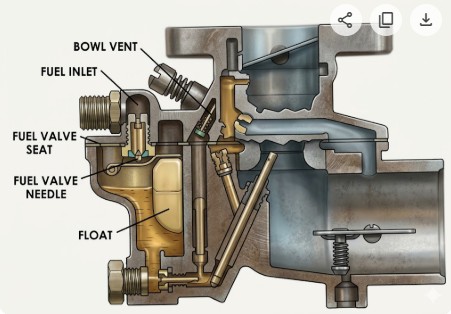
Zenith 68 Fuel System
The fuel supply system (or float system) of the Zenith 68 carburetor is designed to maintain a constant level of fuel in the bowl to ensure consistent metering across all engine speeds and loads.
Based on the technical manual, the operation of this system is as follows:
1. Fuel Inlet and Entry
Fuel from the supply line enters the carburetor through a threaded inlet (typically 1/8-27 inch pipe thread).The fuel first passes through a filter screen and fitting, which protects the system from contaminants, before reaching the fuel valve (needle and seat).
2. Float and Needle Valve Operation
The fuel level in the fuel chamber is regulated by a duplex float assembly.
-
Dynamic Regulation: Unlike a simple on-off switch, the fuel valve assumes a regulated opening. The float holds the needle at a position that allows just enough fuel to enter to match the engine's current demand.
-
Angular Operation: The "duplex" design of the float allows the carburetor to maintain proper fuel metering without flooding even when the engine is operated at extreme angles, which is common in the industrial and agricultural equipment where the Model 68 is often used.
3. Fuel Bowl Venting
The Model 68 is a "balanced" carburetor. To ensure that the fuel flows correctly through the jets, the pressure in the fuel bowl must be synchronized with the pressure at the air intake.
-
Internal Venting: The bowl is vented internally to the air entrance (atmospheric side of the venturi).
-
Self-Correction: If an air cleaner becomes dirty and restricts airflow (lowering the pressure at the intake), the pressure in the fuel bowl is equally reduced.
This "back suction" prevents the mixture from becoming too rich due to the air restriction.
4. Technical Specifications for Maintenance
-
Float Level: For most Zenith 68 models, the standard float setting is 1-5/32 inches. This is measured from the machined surface of the bowl cover (with the gasket removed and the cover inverted) to the top of each float pontoon.
-
Adjustment: Adjustments are made by carefully bending the float lever close to the float body. The pontoons must be centered and at right angles to the machined surface to move freely on the float pin.
