
The Role of the Carburetor
The carburetor's role is to provide a flammable blend of fuel and air to the engine's intake manifold. Depending on the engine's needs, the carburetor regulates the amount of fuel mixed with the air, delivering more fuel for high power requirements and conserving fuel for efficient cruising.
The Engine and its Relationship with the Carburetor The interaction between the engine and the carburetor can be likened to the workings of a suction pump. Every time a piston descends on its intake stroke, a partial vacuum is formed in the cylinder. This vacuum draws the fuel-air mixture from the carburetor and intake manifold into the cylinder via the opened intake valve. See Figure 1. In a hypothetical situation where an engine operates at a single speed and load, the carburetor could simply be a nozzle spraying fuel from a gravity-fed tank into the intake manifold. Fig 2. Once the fuel flow rate has been adjusted for a satisfactory mixture, no further changes would be necessary.
The Venturi Principle
Given that an automobile engine's conditions are continuously changing, the carburetor must adapt the fuel flow to these fluctuations. The venturi in the carburetor facilitates this by controlling the fuel discharge during typical cruising speeds. The venturi is a deliberately designed constriction that momentarily accelerates air as it passes through, resulting in a pressure drop, or vacuum, within the venturi. As engine speed rises, so does the speed of air flow in the carburetor, which in turn intensifies the vacuum in the venturi. This vacuum is utilized to draw the necessary amount of fuel from the carburetor's fuel supply. An experiment illustrating the correlation between air pressure and velocity involves blowing across the top of a piece of paper. You will notice that the paper lifts due to the moving air exerting less pressure than the stationary air beneath the paper, resulting in upward movement. As you increase the air speed, the pressure above the paper reduces correspondingly, lifting the paper even higher. Similar pressure differences form the foundation for carburetor operation.
The Main Metering System

Figure 4 The Holley 847 main metering system, responsible for supplying fuel during cruising speeds, provides a continuous passage from the float chamber to the main discharge nozzle. The nozzle is centrally positioned in the venturi, where the vacuum is most substantial. The float chamber, containing fuel, vents to the carburetor's air inlet, where air pressure is essentially atmospheric, only slightly impacted by the air cleaner's restriction. The air pressure on the fuel in the float chamber is greater than the pressure in the venturi, pushing fuel through the main metering system. This system delivers an efficient fuel to air ratio by weight of approximately one to sixteen, although these proportions may slightly differ for various engines due to their design. The main metering jet, the smallest fuel restriction in the system, primarily manages the fuel flow.
Air Bleeds
For fuel to be thoroughly burned during the piston's power stroke, it must be vaporized. Fuel that enters the cylinders in a liquid state burns too slowly and is wasted. Air bleed passages assist fuel vaporization by introducing air into the fuel stream before discharge, resulting in a more efficient vaporization process.
Throttle Plate
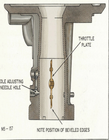
The throttle plate in the carburetor bore controls the engine's power output by determining the amount of fuel-air mixture entering the intake manifold. It is operated by the driver via the accelerator pedal.
The Holley 847 Float System:
Figure 4 The Holley 847's float system ensures a steady fuel supply in the float chamber for the carburetor's fuel metering systems. Fuel under pressure from the fuel pump fills the float chamber via the fuel inlet needle valve. The float, which adjusts with the fuel level in the float chamber, regulates the needle valve to allow just enough fuel to replace what's being used.
Low Power Operation
During idling and low speeds, the carburetor's air flow significantly decreases, and the venturi's vacuum becomes too weak to pull fuel from the main metering system. The near-closed throttle plate limits the air flow into the engine, resulting in a robust manifold vacuum.
The Idle System
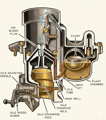
At low power operation, the pressure difference between the manifold and the float chamber drives fuel through the idle system. Fuel flows through the main metering jet into the bottom of the main well, from where it is pulled upward through the idle tube. The tube's narrow tip is a calibrated restriction which primarily meters the fuel flow in the idle system.
Idle Mixture:
Figure 5 Fuel distribution in the manifold is typically less efficient at idle and low speeds than in the normal cruising range. The idle system delivers a rich mixture so that all cylinders will receive enough fuel. The idle mixture can be adjusted to meet the engine's specific needs by setting the idle adjusting needle.
Off Idle Operation:
The idle transfer circuit on a Holley 847 carburetor is a crucial part of how the engine transitions from idle to light throttle smoothly. It operates during the period just after the throttle blades begin to open, before the main fuel circuit takes over.
Here’s how it works:
Holley 847 Idle Transfer Explained
1. Fuel Source – Main Jet and Idle Tube
-
Fuel starts in the float bowl, where the float controls the level.
-
It flows through the main jet into the main well.
-
From there, it enters the idle tube, which meters the fuel for the idle and off-idle circuits.
2. Air Bleed Mixes with Fuel
-
The air bleed plug admits air into the fuel stream to begin emulsifying the mixture before it reaches the discharge ports.
-
This helps atomize fuel for a cleaner burn.
3. Idle Discharge Hole (Idle Port)
-
At closed throttle, fuel flows through the idle discharge hole, located below the throttle blades.
-
This fuel is regulated by the idle adjusting needle, which fine-tunes the idle mixture.
4. Idle Transfer Slot (Off-Idle Transition)
-
As the throttle begins to open, the edge of the throttle blade exposes the idle transfer slot (or idle transfer hole).
-
This slot sits just above the idle port and allows additional fuel to flow in as airflow increases slightly.
Function:
-
The idle transfer slot acts like a bridge between idle and the main circuit.
-
It prevents a flat spot or stumble when the throttle is first opened by delivering extra fuel instantly—before venturi vacuum is strong enough to pull fuel from the main circuit.
Why This Matters
If the throttle blades are:
-
Too far open at idle ? too much of the transfer slot is exposed ? unstable idle or surging.
-
Too far closed ? hesitation or bog off-idle due to fuel starvation.
This is why correct throttle blade position and idle speed screw adjustment are critical. You want to expose only a small portion of the transfer slot at idle (usually a square or slightly taller than wide opening).
Symptoms of Transfer Slot Issues
| Problem | Cause |
|---|---|
| Off-idle stumble or hesitation | Transfer slot not exposed enough |
| Surging at idle | Slot too exposed, pulling from main circuit |
| No effect from idle screws | Throttle blades open too far past transition |
Holley 847 Accelerator System

