
Components and Assembly
-
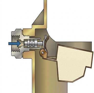
The float assembly utilizes two leak-proof and non-collapsible floats
. -
These floats are attached to a one-piece stainless steel arm that features an adjustment tang
. -
The entire assembly pivots on a hinge pin retainer, which sits in a cradle located inside the main body near the fuel inlet valve
. -
A float baffle is positioned directly between the floats and the adjustment tang
. When installing the assembly, this baffle must be placed with its tabs pointing downward .
Mechanical Operation
-
The core operation of the float system relies on a highly sensitive mechanical relationship with the fuel inlet valve. There is approximately a ten-to-one ratio of movement between the fuel inlet valve and the floats
. -
Because of this high ratio, even a very slight change in the position of the fuel inlet valve will cause a significantly large change in the overall float level setting
. -
The actual torque tightness of the fuel inlet valve directly affects the float position
. Therefore, the valve must be torqued to a specific 200 inch-pounds before checking or setting the float level .
Adjustment Procedure
-
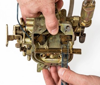
The 2280 uses a dry float setting method, which is performed on the bench with the air horn removed
. -
To take an accurate measurement, the main body is inverted so that the natural weight of the floats forces the needle against its seat
. -
While holding the hinge pin retainer fully seated in its cradle, a "T" type scale is used to measure the distance from the surface of the fuel bowl to the toe of each float
. Both floats must measure at the exact same height; if they do not, the float arms must be bent to equalize them . -
To lower the float level: Bend the adjustment tang toward the fuel inlet needle
. -
To raise the float level: Bend the adjustment tang toward the baffle
.
Adjust the Holley 2280 Float Level
1. Preparation
-
First, remove the air horn from the carburetor
. -
Before taking any measurements, verify that the fuel inlet valve is completely tight. The specifications call for it to be torqued to exactly 200 inch-pounds
.
2. Measuring the Float Height
-
Invert the carburetor's main body
. This allows the natural weight of the floats to force the needle firmly against its seat . -
Place your finger against the hinge pin retainer to ensure it remains fully seated in its cradle
. -
Use a "T" type scale to measure the distance from the surface of the fuel bowl directly to the toe of each float
. -
This measurement must be exactly the same for both floats
. If they are uneven, you must bend one of the float arms to equalize their height .
3. Adjusting the Float Level
If the overall float height needs to be changed after taking your measurements, adjust the floats by carefully bending the adjustment tang on the float arm:
-
To lower the float level: Bend the float tang toward the fuel inlet needle
. -
To raise the float level: Bend the float tang toward the float baffle
.
