
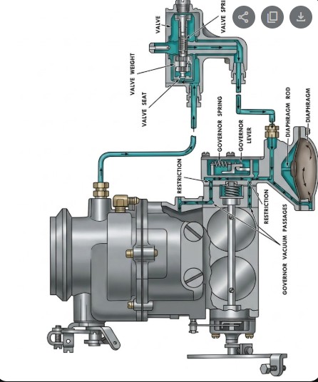
How the 2110 Governor Works?
The Holley 2110 (often found in Ford and Mercury trucks or used as a "Bug Spray" aftermarket carb) utilizes a vacuum-controlled governor system. Unlike mechanical governors that use centrifugal weights on the engine, this system uses air velocity and vacuum pressure to prevent the engine from overspeeding.
Based on the diagram and technical operation of these units, here is how the cycle works:
1. The Speed Sensing Unit (Top Component)
The assembly at the top of your diagram is the Governor Valve. This is typically driven by the engine (often via the distributor or a separate drive).
-
Centrifugal Force: Inside this housing, there is a Valve Weight. As engine RPM increases, centrifugal force pulls this weight outward against the Valve Spring.
-
The Orifice: When the engine reaches its pre-set speed limit, the weight moves far enough to close (or restrict) the Valve Seat.
2. Vacuum Signal Transmission
The carburetor and the governor are connected by the Governor Vacuum Passages (the lines with arrows in your diagram).
-
Normal Running: Under the limit, air/vacuum flows freely through the lines.
-
At the Limit: When the top governor valve closes, it restricts the flow. This causes a buildup of vacuum in the line leading down to the Diaphragm on the side of the carburetor.
3. The Diaphragm and Throttle Control
The large circular housing on the right of the carburetor contains a Diaphragm connected to a Diaphragm Rod.
-
Closing the Throttle: When the vacuum signal from the top valve becomes strong enough, it pulls the diaphragm inward.
-
Overriding the Driver: This rod is connected to the Governor Lever on the throttle shaft. Even if your foot is floored, the diaphragm pulls the throttle plates toward the closed position.
-
Balance: The Governor Spring (visible near the lever) acts as a counter-force. The system reaches an equilibrium where it "governs" the engine at a steady maximum RPM by constantly adjusting the throttle plate position independently of the linkage.
