
Carburetor Identification & Engine Applications
The carburetor number is stamped on the top of the fuel bowl near the bowl vent valve
-
Engine Type: 199" and 232" 6-Cylinder engines with "Engine Mod" systems for emission control
. -
Main Jet Correction: For 1968 Rogue 232" engines (built prior to code 909L18) using the R-4102-A, replace the rich #55 main jet with a #54 jet
.
Adjustment Specifications
Critical Adjustment Procedures
Float Level
-
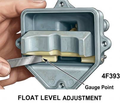
Method: Invert the fuel bowl and measure the distance between the float and the bowl at both ends
. -
Adjustment: Push on the center of the float to raise it or pull to lower it
. Make the float level. -
CAUTION: Do not allow the float tab to contact the Viton-tipped inlet needle during adjustment, as compression can damage the tip and cause leaks
. 
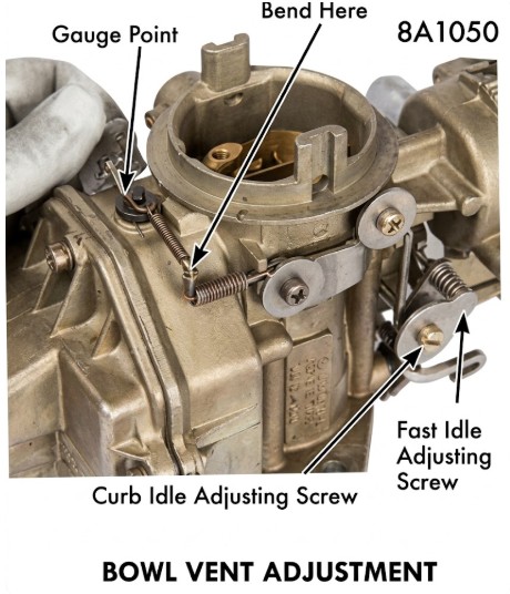
To adjust the bowl vent on a Holley 1931 carburetor using the provided image as a guide, follow these steps:
Preparation
-
Set Curb Idle: Before adjusting the vent, ensure the engine's curb idle is set correctly. The Curb Idle Adjusting Screw (indicated at the bottom left of the linkage) must be at its normal operating position against the throttle lever.
-
Close the Choke: Ensure the choke valve is fully open so the fast idle cam is not interfering with the throttle position.
Adjustment Procedure
The goal of this adjustment is to ensure the vent valve opens a specific amount when the throttle is at idle.
-
Step 1: Identify the Gauge Point Place a feeler gauge or a specific wire gauge (refer to your specific vehicle service manual for the exact thousandths required, often around 0.015" to 0.030") between the Gauge Point indicated in the image and the vent valve lever.
-
Step 2: Check the Gap With the throttle at the curb idle position, check the clearance at the vent valve. The valve should just begin to open or maintain the specified gap.
-
Step 3: Perform the Bend If the clearance is incorrect, locate the adjustment tang labeled "Bend Here" on the vent rod linkage (near the spring).
-
To increase the gap: Bend the tang downward/away.
-
To decrease the gap: Bend the tang upward/closer.
-
Verification
-
Operate the throttle linkage manually to ensure the vent moves freely and closes completely when the throttle is opened off-idle.
-
Check that the Fast Idle Adjusting Screw (bottom right) does not prevent the throttle from returning to the curb idle position during this measurement.
Note: Proper bowl vent adjustment is critical for preventing "hot soak" starting issues, as it allows fuel vapors to escape the float bowl when the engine is idling or turned off.
Idle Mixture
-
1968 Models: Set idle speed 50 RPM low, turn mixture screw counterclockwise until RPM drops, then clockwise for maximum speed, then slightly further in until that maximum speed is just regained (lean-best idle)
. -
1969 Models: Use the highest RPM reading at "lean best idle" setting. These models feature plastic idle limiter caps to restrict travel for emission control
. 
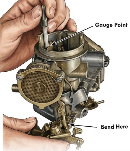
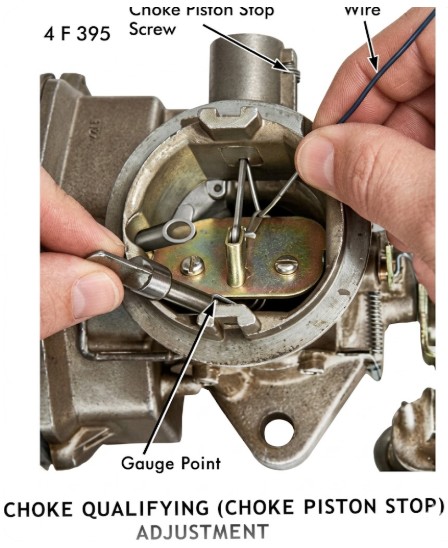
To adjust the Choke Qualifying (Choke Piston Stop) on a Holley 1931 carburetor, follow these instructions based on the provided image. This adjustment ensures the choke plate opens to the correct "pulldown" gap immediately after the engine starts.
Adjustment Procedure
1. Prepare the Linkage
-
Close the choke valve completely.
-
As shown in the image, use a Wire or small hook to pull the choke piston linkage upward until the piston is seated against its stop. You want to simulate the vacuum that pulls the piston down when the engine is running.
2. Measure the Gap
-
Insert a drill bit or wire gauge of the specified size (refer to your technical data sheet) at the Gauge Point.
-
The measurement is taken between the lower edge of the choke valve and the inner wall of the air horn.
3. Adjust the Piston Stop
-
If the gap needs correction, locate the Choke Piston Stop Screw at the top of the choke housing.
-
To increase the gap: Turn the screw counter-clockwise (outward) to allow the piston to travel further.
-
To decrease the gap: Turn the screw clockwise (inward) to limit the piston travel.
Technical Notes
-
Precision is Key: This is often referred to as the "Qualifying" adjustment because it qualifies the initial air-fuel mixture for a cold start. If the gap is too small, the engine will "load up" and stall from being too rich; if it's too large, the engine will lean out and die.
-
Final Check: Ensure the choke valve moves smoothly from the fully closed position to the qualified open position without any binding in the linkage or the piston bore.
Accelerating Pump
The throttle lever has three holes for the pump link
-
#1 Hole: Used for R-4294-A
. -
#2 (Center) Hole: Used for R-3966-A, R-3968-A, and R-4102-A
. -
#3 Hole: Used for R-3967-A
.
