HOW IT WORKS
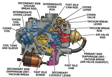
The 2SE carburetor on the 4 cylinder engine uses a single vacuum break unit that is mounted on the idle speed solenoid bracket located on the primary side of the carburetor.
The choke system operates as follows:
When the engine is cold, prior to starting, depressing the accelerator pedal to the floor opens the throttle valve. This allows tension from the thermostatic coil to close the choke valve and also rotates the fast idle cam so the high step is in line with the fast idle cam screw on the throttle lever. As the throttle is released, the fast idle cam screw comes to rest on the high step of the fast idle cam, thus providing enough throttle valve opening to keep the engine running after cold start. During cranking, engine vacuum below the choke valve pulls fuel from the idle system and main discharge nozzle. This provides adequate enrichment for good cold starts.
When the engine starts and is running, manifold vacuum is applied to the primary vacuum break unit. This moves the diaphragm plunger in until it strikes the rear cover, thereby opening the choke valve to a point where the engine will run without loading for stalling. As the engine warms up, heat gradually relaxes tension of the thermostatic coil to allow the choke valve to continue opening. Through inlet air pressure pushing on the off-set choke valve and the weight of the linkage pulling the choke valve open, the choke valve continues to open until it is fully open when the engine can run at normal air/fuel mixtures.
This carburetor is equipped with an electric choke. An electrically actuated ceramic resistor in the electric choke assembly heats the thermostatic coil which gradually relaxes its spring tension so that air velocity through the air horn can continue to open the choke valve. This continues until the engine is warm. At this point, the choke coil tension is completely relaxed and the choke valve is wide open.
The fast idle cam has graduated steps so that fast idle engine speed is lowered gradually during the engine warm up period. The fast idle cam follows rotation of the choke valve. When the choke valve is completely open and the engine is warm, the fast idle am screw on the throttle lever will be off the steps of the fast idle cam. At this point, the idle speed screw or solenoid controls normal engine idle speed.
An unloader mechanism is provided should the engine become flooded during the starting period. The unloader partially opens the closed choke valve to allow increased air flow through the carburetor to lean out the overly rich mixtures. This is accomplished by depressing the accelerator pedal to the floor so that wide open throttle is obtained. When this is done, a tang on the throttle lever contracts an arm on the fast idle cam and forces the choke valve partially open. The extra air leans out the fuel mixture enough so that the engine will start.
The 2SE carburetor on the 6 cylinder engine uses a dual vacuum break system. The front (primary side) vacuum break unit with bracket is mounted on the air horn and the secondary unit is mounted on the idle speed solenoid bracket located on the secondary side of the cabruretor.
The main (primary side) vacuum break diaphragm opens the choke valve. When the choke valve moves to the vacuum break position, the fast idle cam screw will drop from the high step on the fast idle cam to the next lower step (second step) when the throttle is opened.
As the engine manifold is wetted and friction decreases after start, the secondary vacuum break gradually opens the choke valve further.
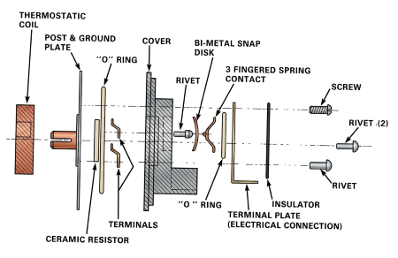
A ceramic resistor in the electric choke assembly is heated by an electric current and the resistor warms the thermostatic coil for precise timing of choke valve opening for good engine warm-up performance.
The electric choke receives an electric current operating through the engine oil pressure switch whenever the engine is running. The electric current flows to a ceramic resistor that is divided into separate sections - a small center section for gradual heating of the thermostatic coil, and a large outer section for additional rapid heating of the thermostatic coil.
The ceramic resistor functions as follows:
AIR TEMPERATURE BELOW 50*F (10*C)
Electric current, applied to the small section of the ceramic resistor causes the section to heat up and warm the thermostatic coil which allows gradual opening of the choke valve for good cold engine warm up performance. As the small section of the ceramic resistor continues to produce heat, a temperature-sensitive bi-metal disk causes a spring loaded contact to close also applying electric current to the large section of the ceramic resistor causing the large section to heat up. Heat from the larger section of the ceramic resistor increases the rate of heat flow to the thermostatic coil for more rapid opening of the choke valve.
AIR TEMPERATURE BETWEEN 50*F (10*C) AND 70*F (21*C)
Electric current applied to the small section or both the small and large sections of the ceramic resistor depending upon the temperature, will produce the required heat to warm the thermostatic coil to control choke valve position for good engine performance in these temperature ranges.
AIR TEMPERATURE 70*F (21*C) OR ABOVE
Electric current is applied directly to both the small section, and through the spring contact, to the large section of the ceramic resistor to provide a rapid heating of the thermostatic coil for great choke valve opening when leaner air/fuel mixtures are desired at warmer ambient temperatures.
NOTE: Ground contact for the electric choke is provided by a metal plate located at the rear of the choke assembly. Do not install a choke cover gasket between the electric choke assembly and the choke housing
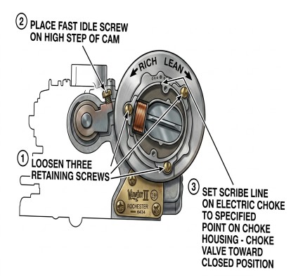
The electric choke assembly is indexed properly by aligning the scribe mark on the front cover with the specified index mark on the choke housing.
ADJUSTMENTS
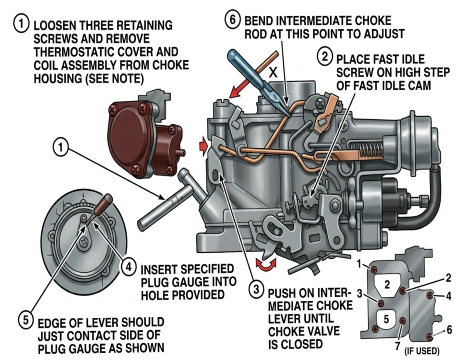
- Loosen three retaining screws and remove thermostatic cover and coil assembly from choke housing
- Place fast idle screw on high step of fast idle cam
- Push on intermediate choke lever until choke valve is closed
- Insert specified plug gauge into hole provided
- Edge of lever should just contact side of plug gauge as shown
- Bend intermediate choke rod at this point to adjust
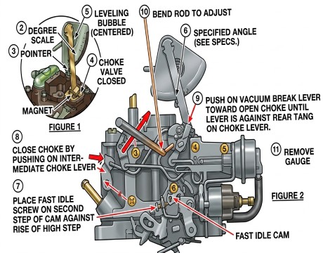
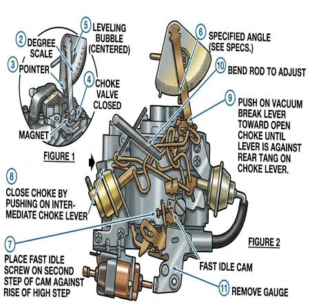
FAST IDLE CAM (CHOKE ROD) RELATION ADJUSTMENT (4 CYLINDER)
- FIGURE 1
- Choke coil lever adjustment must be correct and fast idle adjustment must be made before proceeding.
- Use choke valve measuring gauge if you have one. Tool may be used with carburetor on or off engine. If off engine, place carburetor on holding fixture so that it will remain in same position when gauge is in place
- Rotate degree scale until zero is oppostie pointer
- With choke valve completely closed, place magnet squarely on top of choke valve
- Rotate bubble until it is centered
- FIGURE 2
- Rotate scale so that degree specified for adjustment is opposite pointer
- Place fast idle screw on second step of cam against rise of high step
- Close choke by pushing on intermediate choke lever
- Push on vacuum break lever toward open choke until lever is against rear tang on choke lever
- To adjust, bend fast idle cam rod until bubble is centered
- Remove gauge
4 Cylinder Passenger
6 Cylinder Truck
ELECTRIC CHOKE SETTING ADJUSTMENT
- Loosen three retaining screws
- Place fast idle screw on high step of cam
- Set scribe line on electric choke to specified point on choke housing - choke valve toward closed position