
Carter Brass Bowl Carburetor Dodge 1930 Carburetors 153S  |  | ||||||||||||||||||||||||||||||||||||||||||||||||||||||||||||||||||||||||||||||||||||||||||||||||||||||||||||||||||||||||||||||||
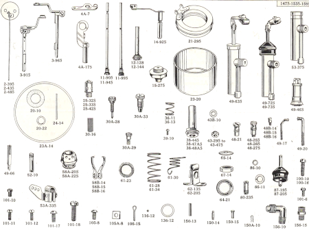
| Specifications Flange Size: 1 1/8", Upper Well: Depth from stand pipe seat, 1/4" Lower Well: 11/32" ID Float Level: Top of float to be 11/16" from machined surface of casting at point opposite needle, with needle seated. Inside Vent: No. 50 drill. Gasoline Intake: Square vertical needle. No. 38 hole in needle seat. Gas Line Connection: 5/16" Low Speed Jet Tube: Jet, No. 70 drill. Idle Port: Length .176", Width: .030". Opening above valve with valve closed tight: .034" to .038" By Pass: under idle port No. 54 drill. Set Idle Adjustment Screw: 3/4 to 1 1/4 turn open. For richer mixture, turn screw in. Do not idle engine below 300 RPM with spark retarded. Main Sell Jet No. 55 drill. Multiple Jet Nozzle: Vertical jet, No. 48 drill. Top I.D. No. 26 drill size. Accelerating Jets (Combination No. 70): 4 No. 60, 9/16" from top. 2 No. 55, 1 5/16" from top. 2 No. 55, 1 11/32" from top. Metering Rod: Diameter top, .070"; bottom .060"; length 4 57/64". Standpipe: Flare top 7/16" ID with 5/16" venturi. One No. 49 air hole in base. Two air slots .250" - .254" high by .380" - .385" wide. Accelerating Pump: Low pressure type: Discharge jet, No. 72 drill; Feed to ball check, No. 45 drill. Connect plunger shaft to give longest stroke for winter driving, using shorter stroke for normal or hot weather. Viewing Carburetor From Side Opposite Air Intake Choker (compensating cone type): In venturi, lever at left. When open points down. Throttle Lever: 1 1/4" long at left side. In center of travel points up. Tube Clamp: On air intake. | Setting Float Level | ||||||||||||||||||||||||||||||||||||||||||||||||||||||||||||||||||||||||||||||||||||||||||||||||||||||||||||||||||||||||||||||||
| Carburetor Adjustments If carburetor loads up after considerable service, float level should be checked. Wear on lip of float level should be checked. Wear on lip of float lever will raise float level. Bending lip of float lever down will raise float level; bending lever up will lower float level. Only a slight bend is needed. If motor stalls while idling, reset idle adjustment screw and throttle valve adjusting screw. If these adjustments do not correct the trouble, remove low speed jet tube and clean thoroughly with compressed air. Examine soldered joint in tube for air leaks and see that tube seats air tight in body casting, top and bottom. If not, replace with a new tube of identical specifications. Never change a low speed jet tube from one carburetor to another. Increased resistance on foot throttle indicates a clogged pump jet. Pump jet should be removed and cleaned with compressed air, which, in many cases, will remove the dirt or lint. All jets and ball checks must be seated gasoline tight. Poor acceleration may be due to damaged or worn plunger leather in accelerating pump, corrosion in pump cylinder, loose or cracked cylinder, cracked plunger or bent pump arm. Pump stroke is adjustable for high or low temperatures. Set plunger pin in hole to give longest stroke for cold weather. Set pin in hole giving shorter stroke for hot weather driving. | |||||||||||||||||||||||||||||||||||||||||||||||||||||||||||||||||||||||||||||||||||||||||||||||||||||||||||||||||||||||||||||||||
 |
|
-
Carburetor Parts
- by Make & Model
- Aero Coach Carburetor Parts
- Alfa Romeo
- American Bantam
- American General
- American LaFrance
- American Motors Nash Rambler
- Auburn
- Audi
- Austin
- Autocar
- Available Truck
- BMW
- Bristol
- Buick
- Cadillac
- Checker
- Chevrolet
- Chevrolet/GMC Trucks
- Chord
- Chrysler
- Cortina
- Desoto
- Dodge
- Dodge Truck
- Edsel
- Federal Truck
- Fiat
- Ford/Mercury
- Ford Truck
- Goliath
- Graham Paige
- Hall Scott
- Hillman
- Honda
- Hudson
- Hupmobile
- I.H.C. International
- Innocenti
- Innocenti
- Jaguar
- Jeep/Willys
- Jensen Healey
- Kaiser Frazer
- Lafayette
- Lancia
- LaSalle
- Latham Supercharger
- Legonda
- Lincoln
- Lotus
- Mazda
- Mercedes
- MG
- Morgan
- Morris
- Nissan/Datsun
- Oldsmobile
- Opel
- Packard
- Plymouth
- Plymouth Arrow
- Pontiac
- Riley
- Rover
- Stewart
- Studebaker
- Studebaker Truck
- Terraplane
- Toyota
- Triumph
- Vanden Plas
- Volvo
- White
- Wolseley
Scroll to see more - by Carb Types
- by Part Type
- Accelerator Pump
- Ball Stud
- Brass Fittings
- Bushings
- Carburetor Kits
- Clean Out Plugs
- Clips & Retainers
- EFE Heater Gaskets
- Electric Choke Conversion Kits
- Fuel Filters
- Floats
- Gaskets
- Idle Mixture Screws
- Check Balls & Check Weights
- Fuel & Vacuum Hose
- Jets & Metering Rods
- Needle and Seat
- Power Valves & Jets
- Pull-Off
- Rods & Linkage
- Rubber Caps
- Screws
- Thermostats
- Throttle Position Sensors and Solenoids
- Float Pins
- Springs
- Sediment & Fuel Bowl
- Washers & O-Rings
- Choke & Throttle Shafts
- Carburetor Dashpots
- Carburetor Tubes
- Marine
- Acadia
- Aero
- Aeroceanic Motors
- Aquanautics
- Chris Craft
- Chrysler Marine
- Chrysler Outboard
- Clinton Outboard
- Crosley Marine Carburetor Parts
- Crusader Marine Carburetor Parts
- Daytona
- Dearborn
- Ford Marine
- Gray Marine
- Grumman Allied
- Holley Universal
- Johnson Evinrude Marine Outboard
- Kermath Marine
- Kiekhaefer Carburetor Parts
- Kohler
- Lathrop Marine
- Marine Chokes
- Medalist Marine
- Mercury Marine
- Mercury Marine Outboard
- Mercury Mariner
- Montgomery Ward Sea King Outboard Parts
- Nordberg Marine
- Oldsmobile Marine
- OMC Marine Parts
- Outboard Motors
- Owens
- Palmer Marine
- Pleasure Craft
- Redwing Marine
- Revley Marine
- Salmon Stiles
- Scripps Marine
- Tillotson Marine Outboard
- Universal Motors
- Volvo Penta
- Yamaha Outboard
- Ag & Industrial
- Acadia
- Allis Chalmers
- American Tractor
- Automatic Transportation Company
- Avco
- Baker
- Bardco
- Bay City
- Buda
- Buffalo Springfield
- Burmeister Wain
- Butler Bin
- Case
- Caterpiller
- Champ Lift Truck
- Clark Agriculture
- Chicago Pneumatic
- Chrysler Industrial
- Climax Engineering
- Clinton
- Clyde Iron Works
- Cockshutt
- Continental
- Crosley
- Davey
- Divco
- Duplex
- Earthmaster
- Easthope Brothers
- Eaton Corporation
- Elwell Parker Company
- Fairbanks Morse
- Fairmont
- Fate Root Heath
- Federal Machine
- Ford
- Gibson
- Gordon Smith
- Hercules
- Hobart Brothers
- Hollingsworth
- Hough
- Holtkamp
- Huber
- Hyster
- IHC Carburetor Parts
- Ingersoll Rand Industrial
- Intercontinental
- Jacques
- Jaeger
- John Deere Tractor
- Joy Manufacturing
- Kaiser Industrial
- Kalamazoo Railroad
- Kohler Industrial
- Kurtz Root
- Leroi
- Lincoln Electric Industrial
- Lunnenberg
- Lycoming Industrial
- Massey Ferguson
- Mercury Manufacturing
- Miller Applications
- Minneapolis Moline
- Motor
- Motoresearch
- National Farm Agriculture
- New Holland
- New Idea Farm Equipment
- Novo
- Oliver Carburetor Parts
- Onan Industrial Carburetor Parts
- Owatonna
- Palmer
- Perkins
- Pettibone
- Pioneer Agriculture & Industrial
- Railcar
- Ready Power
- Redwing
- Reiner
- Robinson Machinery
- Russell Agriculture & Industrial
- Schramm
- Seagrave
- Service Caster
- Sullair
- Tenant
- Thermo King
- Thew Shovel
- Toro
- Towmotor
- Toyota Forklift
- Transicold
- Transitier
- Universal Motors
- U.S. Motors
- Volvo
- Waukesha Industiral
- Western Gear
- White Motors Truck Carburetor Parts
- Winpower
- Wisconsin Motors
- Yale and Towne
Scroll to see more - Odds & Ends
- by Make & Model
-
Carburetors
-
Fuel Injector Parts
-
Fuel Injector Cleaning
-
Manuals
-
Technical
-
Swag
