
FLOAT LEVEL ADJUSTMENT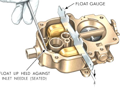
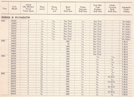
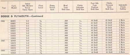
Hold needle valve against its seat as shown and measure from top of floats (at center) to top of main body. If proper gauge is not available, the float level should be as listed in the spec sheet. If an adjustment is necessary, bend lip of float arm as required.
ACCELERATOR PUMP TRAVEL
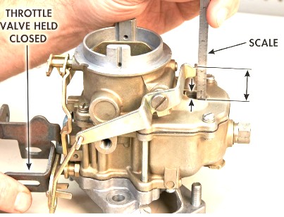
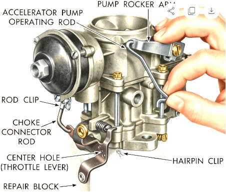
- Back off idle speed adjustment screw. Open choke valve so that throttle valve can be completely seated in carburetor bore. Be sure pump connector rod is in center hole of throttle lever.
- Close throttle valve tightly. Then measure distance between top of air horn and end of plunger shaft as shown.
- If dimension is not as specified in the table, bend pump connector rod at the lower angle as required.
BOWL VENT ADJUSTMENT
1962: If pump rod is installed in either the long or short stroke hole, it will be necessary to more the hair pin clip (directly under bowl vent valve) either up or down to compensate for the change in order to obtain correct bowl vent clearance.
1963-67: This adjustment automatically adjusts the accelerator pump as well. The procedure is as follows:
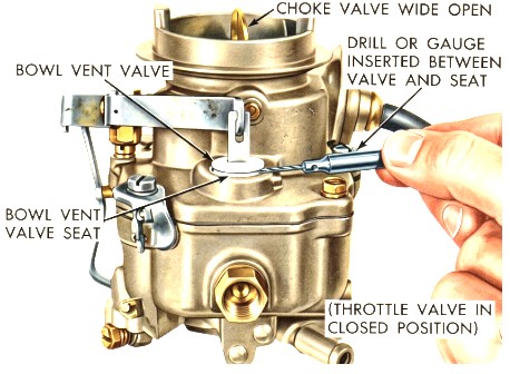
- Back off idle speed adjusting screw. Open choke valve so that when throttle valve is closed the fast idle adjusting screw will not contact fast idle cam.
- Be sure pump operating rod is in center hole in throttle lever and that bowl vent clip on pump stem is in center groove.
- Close throttle valve tightly. It should be possible to insert a drill of the specified size between bowl vent and air horn.
- If an adjustment is necessary, bend pump operating rod at the lower angle as required to obtain the correct bowl vent opening.
NOTE: This is an important adjustment since too much lift at the bowl vent will result in considerable loss in low speed fuel economy. If the pump operating rod is moved to either the short or long stroke position, a corresponding change must be made in the location of the bowl vent clip, and the amount of lift of the bowl rechecked and adjusted.
CHOKE UNLOADER ADJUSTMENT
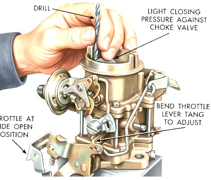
Hold throttle valve in wide open position. Insert a drill of the specified size between upper edge of choke valve and inner wall of air horn. With a finger lightly pressing against choke valve, a slight drag should be felt as the drill is being withdrawn. If an adjustment is necessary, bend unloader tang on throttle lever as required.
FAST IDLE CAM POSITION
1962-63:
- Open throttle valve and hold choke valve fully closed; then close throttle valve. This will position fast idle cam to fast idle position.
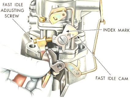
- Release choke valve slowly. This positions fast idle cam to fast idle. The index mark on cam should split the center of the fast idle adjusting screw as shown.
- If an adjustment is necessary, bend fast idle connector rod at the angle as required.
1964-67:
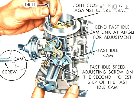
- With fast idle speed adjusting screw contacting the second highest step on the fast idle cam, move choke valve toward closed position with light pressure on choke shaft lever.
- Insert specified drill between choke valve and wall of air horn. If an adjustment is necessary, bend fast idle rod at upper angle until correct valve opening has been ontained.
VACUUM KICK ADJUSTMENT
1964-67: The choke diaphragm adjustment controls the fuel delivery while the engine is running. It positions the choke valve within the air horn by action of the linkage between the choke shaft and diaphragm. The diaphragm must be energized to measure the vacuum kick adjustment. Use a vacuum source, or vacuum supplied by another vehicle.
Adjust as possible:
- If adjustment is to be made with the engine running, back off the fast idle speed screw until choke can be closed to the kick position with engine at curb idle.
- NOTE the number of screw turns required so that fast idle can be returned to original adjustment
- If auxiliary vacuum source is to be used, open throttle valve (engine not running) and move choke to closed position. Release throttle first, then release choke.
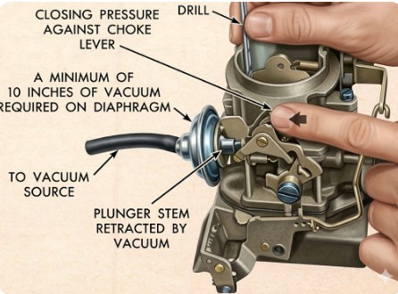
- When using an auxiliary vacuum source, disconnect vacuum hose from carburetor and connect it to hose from vacuum supply with a small length of tube to act as a fitting. Removal of hose from diaphragm may require forces which change the system. Apply a vacuum of 10 inches or more of mercury.
- Insert specified drill between choke valve and wall of air horn. Apply sufficient closing pressure on lever to which choke rod attached to provide a minimum stroke valve opening without distortion of diaphragm link. Note that cylindrical stem of diaphragm will extend as internal spring is compressed. This spring must be fully compressed for proper measurement of vacuum kick adjustment.
- An adjustment will be necessary if a slight drag is not obtained as drill is being removed. Shorten or lengthen diaphragm link to obtain correct choke opening. Length changes should be mae carefully by bending (open or closing) the bend provided in the diaphragm link. Do not apply twisting or bending force to diaphragm
- Reinstall vacuum hose on correct carburetor fitting. Return fast idle screw to its original location if disturbed as suggested in the first step.
- Check the adjustment as follows: with no vacuum applied to diaphragm, choke valve should move freely between open and closed positions. If movement is not free, examine linkage for misalignment or interferences caused by bending operation. Repeat adjustment if necessary to provide proper link operation.
SPRING STAGED CHOKE ADJUSTMENT
1963-68: The spring staged choke is a device incorporated in the choke mechanism that limites the choke blade closing torque when cranking the engine at temperatures below zero. Thus the spring staging of the choke is a better match for the engine's starting mixture requirements at low temperatures.
To check the spring stages choke for correct operating clearance, proceed as follows:
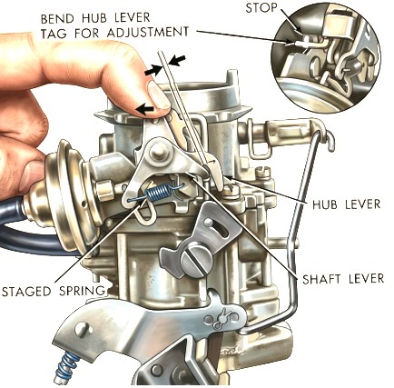
- Push on hub lever with finger at closed choke position. A small opening should exist between shaft and hub levers as indicated.
- Using a drill or gauge, measure the opening which should be from .010 to .040".
- If adjustment is necessary, bend hub lever tang until correct opening is obtained.
CHOKE ADJUSTMENT
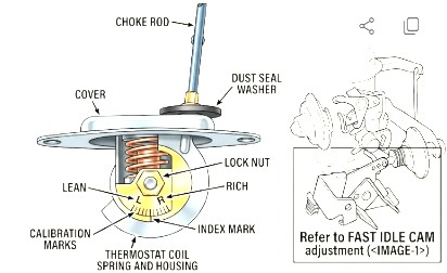
Loosen mounting post luck nut and turn mounting post with screwdriver until index mark on disc is positioned as listed in the spec chart. Hold in this position with screwdriver and tighten lock nut.
NOTE: Screwdriver may be held in a vise so that one hand may be used to support housing while tightening nut. After adjustment is completed and coil housing and rod and carburetor are installed on engine, lift cover disc and open and close choke valve manually to see if connector rod clears sides of hole in housing cover without binding. If rod does not clear housing cover without binding, replace with a new unit since connecting rod cannot be bent without affecting calibration.
IDLE SPEED ADJUSTMENT
C.A.P. Carburetors
To make an idle speed adjustment on these models, Chrysler recommends the use of an ignition tachometer and an exhaust gas analyser in good condition.
The procedure follows:
- Have engine running at normal operating temperature, and ignition timing checked and set to specification given on the spec chart
- Air cleaner installed
- On 6-cylinder models turn headlights on (high beam position)
- Automatic transmission in neutral (not in park position)
- Turn air conditioning off (if equipped)
- Connect ignition tachometer
- Insert probe of gas analyser as far as possible (2 ft minimum) in tail pipe. On dual exhause cars, use left side tail pipe (side opposite heat valve)
IMPORTANT: Be certain that probe and connecting tubing are free of leaks to prevent erroneous readings. If a garage exhaust system is used to conduct the exhaust gases away, a plenum chamber (enclosed air chamber) or other means must be used to reduce the vacuum of the exhaust system to 1/2 inch water or less.
- Connect gas analyser, warm up and calibrate according to manufacturer's instructions.
- Place clamp on hose between distributor vacuum control valve and intake manifold
- Set idle speed to specifications listed in spec chart
IMPORTANT: When adjusting mixture screws to obtain the air/fuel ratio of 14.2 specified for C.A.P., do not turn mixture screws more than 1/16 turn at a time. The gas analyser is so sensitive that the ratio must be changed by very small increments if accurate readings are to be obtained. The meters read in air/fuel ratio so that a higher reading indicates a leaner mixture and vice versa.
- Adjust each screw 1/16 turn richer (counter-clockwise) and wait 10 seconds before reading the meter
- If necessary, repeat previous step until the meter indicates a definite increase in richness (lower reading). This step is very important since the meter reverses its readings an indicates a richer mixture as the carburetor is leaned out if the carburetor is set very lean
- When it has been established that the meter is indicating a lower reading (richer mixture) when the idle mixture screws are turned in a richer direction, proceed to adjust the carburetor to give the 14.2 air/fuel ratio, turning the screws counter-clockwise (richer) to lower the meter reading and clockwise (leaner) to increase the meter reading
- If the idle speed changes as the mixture screws are turned, adjust the speed to specifications and readjust the mixture as required so that 14.2 air/fuel ratio is obtained at the specified idle speed
- If the idle is rough, the screws may be adjusted, independently to achieve a smooth idle, provided the air/fuel ratio is held at 14.2
- Remove clamp from distributor vacuum valve hose. If the idle speed changes materially, check and adjust the distributor vacuum control valve
DASHPOT ADJUSTMENT
C.A.P. Carburetors
The dashpot is used only on cars equipped with the Cleaner Air Package and manual transmission.
To adjust the dashpot, have the curb idle speed and mixture properly adjusted, and install a tachometer. Position throttle lever so that actuating tab on lever is contacting stem of dashpot but not depressing it. The tachometer should read 2000 rpm if the setting is correct. If not correct, screw dashpot in or out as required, then tighten lock nut on dashpot against the bracket.
SPECIFICATIONS
