
The model BBD is a BB design, dual carburetor with low overall height. Accessible adjustments and removable subassemblies.
- Float circuit
- Low speed circuit
- High speed circuit
- Pump circuit
- Choke circuit
All BBD carburetors prior to 1974 are of the air-bled design incorporating downhill nozzles. 1974 and later models are of solid fuel design with uphill nozzles. The solid-fuel design provides more precise fuel metering to meet emission standards while still maintaining maximum response and drivability. For increased life and smooth operation, the solid fuel design uses a Teflon-coated throttle shaft.
Float Circuit
All fuel enters through the fuel inlet fitting in the bowl. The fuel inlet needle seats directly in this brass fitting and is controlled by the twin or dual floats which are hinged by a float fulcrum pin. The fulcrum pin is held in position by the “horseshoe” retainer. The twin floats follow the contours of the fuel bowl and are designed to provide a stable fuel supply under all conditions. Only a minimum of fuel is maintained in the carburetor, preventing excessive fuel evaporation. This tends to improve warm engine starts.
The float circuit must constantly maintain the specified fuel level as the other circuits are calibrated to deliver the proper mixture only when the fuel is at this specified level. When the fuel level in the bowl drops, the float also drops permitting additional fuel to flow past the inlet needle into the bowl.
The bowl is vented to the inside of the air horn. The bowl vent is calibrated to provide proper air pressure above the fuel at all times. To assure a positive seal, always use a new bowl cover gasket when reassembling. An air leak at this point can result in a mileage complaint.
Float Adjustment
Remove float to adjust. NOTE: To obtain his proper alignment it may be necessary to bend the float lip at either or both arrows “A” and “B”. CAUTION: Never allow the needle to be pressed into the seat when making the adjustment as this might damage the viton tip.
After the float adjustment has been made and set to the manufacturer’s specifications, the float lip must be in the vertical position with the needle lightly seated.
Venting the System
The BBD carburetor also uses an outside bowl vent that opens at the closed throttle position. When the engine is turned off, underhood temperatures increase causing vapors to rise from the fuel in the bowl. The outside vent improves starting characteristics as it prevents vapors from entering the bore of the carburetor by way of the inside vent.
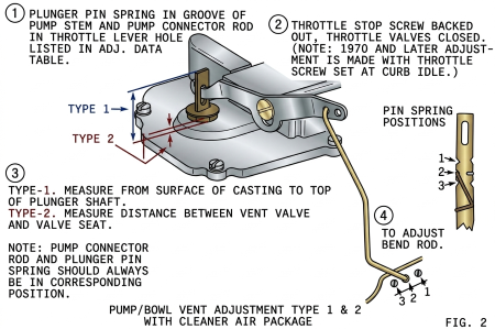
Bowl vapor vent adjustment must be to specifications. If the valve does not open to specifications with throttle valves seated, bowl vapors cannot escape freely and this may cause “hard-hot-starting.” if it opens too far, or hangs open, it will allow an external vent to the bowl, resulting in poor mileage.
Emission Laws effective in 1971 required all outside vents to be routed to a canister to prevent evaporative emissions.
Two Way Bowl Vent
To meet evaporative emission regulations. Late-model BBD’s use a solenoid-controlled two-way bowl vent.
When the ignition switch is in the off position. The spring-loaded diaphragm forces the puck valve to its upper position, thus closing the inside carburetor vent and opening the canister vent. When the ignition switch is turned on, the solenoid is energized moving the puck to its downward position. Thus closing the canister vent and opening the inside carburetor vent.
If the solenoid should fail, venting to the carburetor fuel bowl would be by way of the canister. This change in bowl pressure would affect drivability. An increase in bowl pressure causes a rich condition. Lowering bowl pressure results in a lean condition.
Low Speed Circuit
Fuel for idle and early part throttle operation is metered through the low-speed circuit.
Fuel enters the idle and high-speed wells through the main metering jets. The low-speed jets measure the amount of fuel for idle and early part throttle operation. The by-pass, idle air bleeds, and economizers located in the venture attaching screws are carefully calibrated and serve to break up the liquid fuel and mix it with air as it moves through the passage to the idle ports and idle adjustment screw ports. Turning the idle adjustment screws toward their seats reduces the quantity of fuel mixture supplied by the idle circuit.
The idle ports are slot-shaped. As the throttle valves are opened, more of the idle ports are uncovered, allowing a greater quantity of fuel and air mixture to enter the carburetor bores.
The by-pass, idle air bleeds, economizers, low-speed jets, idle ports, idle adjustment screw ports, as well as the bores of the carburetor flange, must be clean and free of dirt and carbon. Obstructions will cause poor low-speed engine operation.
Idle Adjusting Screw
The idle bleed is into the bore of the carburetor on the atmospheric side of the closed throttle valve. The amount of bleed varies with throttle position.
Idle adjusting screws are used for trimming the idle mixture to individual engine requirements for satisfactory idle.
Emission Laws require the use of idle adjusting screws with limited adjustability. This allows for proper idle adjustment while assuring the emission limits will not be exceeded.
One design uses an Allen screw as a stop as it makes contact with the shoulder on the recessed portion of the idle adjusting screw.
On the flow test, the idle adjusting screw is turned in the counterclockwise direction to the mean rich limit. The Allen screw is then turned in against the recessed shoulder of the idle adjusting screw. The Allen screw hole is then filled with a lead plug.
Another version uses an idle adjusting screw which is completely recessed in the flange of the carburetor.
After final adjustment, it is sealed with a lead plug.
The upper adjusting screw is an air adjustment screw and adjusts the mixtures for both bores.
This air adjustment screw has left-handed threads. Turning the adjusting screw counterclockwise moves the screw inward to richen the air-fuel mixture.
Adjustable Off-Idle Air Bleed
Some older BBD models use an adjustable off-idle air bleed which is adjusted during flow test. This adjustment should never be changed as it cannot be adjusted in the field.
The purpose of the “adjustable off-idle air bleed” is greater control of the air-fuel ratio at flow rates above curb idle, resulting in a substantial reduction in hydrocarbons.
The circuit consists of an adjustable spring-loaded ball check valve located in an air passage to the low-speed circuit.
Closer calibration can be attained by being able to adjust the idle fuel mixture at two different points in the air-fuel ratio curve.
The air bleed valve is set to open at an idle port vacuum of 7 to 12 inches of water which is slightly above the three to four inches at curb idle.
When the throttle is opened slightly, the lower pressure at the idle port opens the air bleed valve to control the air-fuel ratio.
If the rate of acceleration reaches a certain maximum, the vacuum at the idle port will drop below the 7 to 12 inches of vacuum allowing the air bleed valve to seat. This enrichment of the air-fuel mixture is desirable for a high rate of acceleration.
As the bleed port is below the closed position of the choke valve. Air will not enter the air bleed valve until the choke valve is partly open, thus making the automatic air bleed inoperative during the early stages of engine warm-up.
The air bleed valve will open on deceleration from high speed to prevent rich mixtures.
The “adjustable off-idle air bleed” is also used on some AVS models.
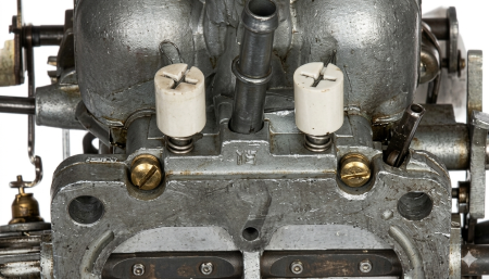
Idle Limiter Caps
All late-model carburetors use idle limiter caps to prevent over-rich idle adjustments.
Idle Restrictors
In addition to limiter caps, some late models use idle restrictors located in the throttle body. The purpose of the restrictor is to limit the maximum air-fuel enrichment available at idle.
Tamperproof Mixture Screws
Same 1979 and later model carburetors will use the hidden “tamperproof idle mixture screws.” These screws are adjusted and sealed at the factory. Adjustment of the sealed idle mixture screws should be performed only when the carburetor will not meet specifications or when a major carburetor overhaul is necessary.
Idle Enrichment System
Some models use an I.E.S., “Idle Enrichment System,” to improve cold engine performance at the initial starting of the engine. Along with this carburetor circuit or system, an electronic timer and vacuum solenoid valve are also used. The timer energizes the solenoid valve during starting and for 35 seconds after start.
When the solenoid is energized it cuts off the EGR system which eliminates any exhaust gas recirculation from taking place. Secondly, it applies manifold vacuum to the idle enrichment diaphragm when the engine coolant is below a predetermined temperature. The manifold vacuum overcomes the spring tension and pulls the diaphragm away from the seat and valve, thereby allowing the valve to seat closing off the air passage.
Cutting off the air supply enriches the idle mixture which allows more fuel to be delivered during starting and for 35 seconds after start. After the 35 second delay period, the electronic timer de-energizes the solenoid valve which allows the EGR system to function and also cuts off the manifold vacuum to the idle enrichment diaphragm.
The spring then pushes the diaphragm against the valve and seat assembly causing the valve to unseat. This in turn allows air to flow through the system and a normal air-fuel ratio to be delivered to the cylinders. The purpose and results are improved hot engine starting by delaying the EGR for 35 seconds and improved cold engine performance after starting by initiating idle enrichment for 35 seconds.
Part 2
Idle By-Pass Assist
Some BBD units incorporate an idle by-pass assist. This passage goes through the main body, and the body gasket. Through a passage in the throttle body and enters below the throttle valve. This extra air through the by-pass allows the throttle valve to close a little more for a given idle RPM. This reduces the CFM airflow over the nozzle tips and prevents the possibility of taking fuel from the nozzles during fast idle operation. It also causes turbulence below the throttle valves to aid air-fuel mixture and distribution.
Idle Solenoid
Many carburetor models use an idle solenoid to prevent “dieseling” or “after run.”
Many things that have been done to lower emissions have enhanced the possibility of dieseling. Higher idle speeds, leaner air-fuel mixtures, retarded ignition timing, higher operating temperature, all contribute to dieseling. When the ignition is turned on, the solenoid is energized moving the plunger outward. The idle RPM is adjusted at the solenoid. When the ignition is turned off the solenoid is de-energized, the plunger moves inward allowing the throttle valves to close enough to virtually shut off the air supply, causing the engine to stop running immediately. Some units have a second adjustment to prevent the throttle valves from closing too tightly.
Air Conditioner Solenoid
The air conditioner solenoid is used in many applications to maintain idle RPM.
The extra load on the engine when the air conditioner is turned on causes a drop in idle RPM.
The solenoid is energized moving the solenoid plunger outward. This outward movement opens the throttle valves (as specified) to maintain idle RPM.
SIS Solenoid
Some later models use an S.I.S. (solenoid idle stop) solenoid. When the air conditioning, rear window de fogger, or any accessory with a heavy load is turned on, the S.I.S. solenoid is energized and the plunger moves outward to open the throttle valves slightly.
The adjustment or the S.I.S. solenoid is on its inward travel rather than the conventional outward travel. Two adjustments are required and must be made in proper sequence, as specified on the solenoid decal.
When the accessory is turned off, a timer gives a two-second delay in de-energizing the solenoid to prevent the engine die out.
SOL-VAC
The sol-vac is also used in many applications. The electrical solenoid is energized when the air conditioning is on, when the hedgehog is in operation, rear window defroster, or any heavy electrical load.
The vacuum portion is activated anytime the air temperature in the air cleaner is below 55 degrees, or anytime the idle drops to 450 R.P.M. At 450 R.P.M. the vacuum section is activated and opens the throttle valves to specifications which is above normal idle. A time delay is used to return the throttle valve to normal idle. If idle drops to 450 R.P.M. the second time, the vacuum unit is again activated, however, the time delay is not in operation. A return to idle then requires increasing engine speed to 1150 R.P.M.
The hedgehog replaces the heat riser. It is a finned type heater element located in the manifold just below the carburetor. It is controlled by a wax pellet-type temperature switch located in the engine block. The hedgehog is on any time the water temperature is below 160 degrees.
Three adjustments are required and must be made in the proper sequence.
Air Bleed Circuit
High Speed Circuit
Fuel for part throttle and full throttle operation is supplied through the high-speed circuit.
The air-bled circuit used prior to 1974 has an emulsion, tube, or vent tube that extends downward into the high-speed well. This tube mixes air with the fuel before it leaves the high-speed well. The air-bled design always uses “downhill” nozzles. The air bleed in the high-speed circuit also serves as an anti-percolator passage.
The solid-fuel design, 1974 and Later, takes solid fuel from the high speed well and bleeds air into the circuit at the top through the extended vent tubes located in the cluster, closer to the tip of the nozzle. The solid-fuel design always uses “uphill” nozzles and gives a closer calibration to meet the emission standards and also serves as an anti-percolator passage.
Diminishing Well Bleeds
Some solid fuel models use diminishing well bleeds. This bleed is subjected to venturi pressure changes that follow engine load conditions. They serve as self-adjusting air bleeds and at or near the wide-open throttle, could deliver fuel.
The two center holes are the pump discharge windows and also the air bleed to prevent pump pull over. A pump pullover is when gas is coming out of the discharge when the accelerator pump isn’t being activated.
Metering Rod
The position of the metering rod in the main metering jet controls the amount of fuel admitted to the discharge nozzle.
The metering rod has varying step diameters which controls the effective size of the main metering jet in which it operates.
Function of the Metering Rod
The two metering rods are yoked to a single step-up piston assembly which rides in a cylinder in the bowl casting. The jets which work with the metering rods are located in the fuel bowl. Note the solid fuel jets are different than those used in the air-bled system.
At part throttle and cruising speeds, increased airflow through the venturi creates a low-pressure area in the venturi. Since the air above the fuel level in the bowl is near atmospheric pressure, fuel flows to the lower pressure area created by the venturi. The fuel flow moves through the main jets to the main nozzle as it picks up air from the air bleeds.
During heavy road load or high-speed operation, the air-fuel mixture must be enriched to provide increased engine power. Power enrichment is accomplished by movement of the metering rods which are attached to a single yoke and piston actuated by the manifold vacuum. The metering rod piston rides on a calibrated spring which attempts to keep the piston at the top of the cylinder. At idle, part throttle, or cruise conditions when manifold vacuum is high, the piston is drawn down into the vacuum cylinder, compressing the vacuum piston spring. The larger diameter of the metering rods will be positioned in the main jets allowing a calibrated amount of fuel flow to the nozzle. Under any operating condition where the tension of the vacuum piston spring overcomes the pull of vacuum under the piston, the metering rods will move upward so the smaller diameter step is in the jet. This permits the necessary additional fuel flow to be metered through the jets.
The metering rods in the solid fuel unit are both mechanically and vacuum operated and must be adjusted. The lifter tab lifts the metering rods mechanically and also limits the amount of lift from the vacuum piston.
Vacuum Step-Up Piston Hex-Head Screw
Never attempt to change the factory setting of the vacuum step-up piston hex-head screw as it will seriously affect performance. This adjustment is made during flow testing and cannot be duplicated in the field.
An air leak past the gaskets sealing the venturi cluster, venturi cover, and tube assembly or the venturi cluster screws will affect both low speed and high-speed performance. To assure a positive seal always use new gaskets and be sure venturi cluster screws are tightened securely.
Manual Altitude Compensator
To meet emission standards at 4,000 feet above sea level, some BBD carburetors use a manual altitude compensator. It consists of a spring-loaded adjustable cap added to the venturi cluster. During pre-delivery of the vehicle for altitude use. The adjusting screw is turned in the counterclockwise direction. The spring forces the cap upwards uncovering the auxiliary air bleeds to the low-speed circuit. In addition to the auxiliary air bleeds, there is an oversized air bleed drilled into the lower section of the venturi cluster assembly and with the cap in its upward position, the air is bled into both the low speed and high-speed circuits to lean out to the altitude calibration required. There is no adjustment. The cap merely opens or closes these additional air bleeds.
Pump Circuit
The accelerating pump circuit provides a measured amount of fuel which is necessary to ensure smooth engine operation for acceleration.
When the throttle is closed, the pump plunger moves upward in its cylinder, and fuel is drawn into the cylinder through the intake check. The discharge check is seated at this time to prevent air from being drawn into the cylinder. When the throttle is opened, the pump plunger moves downward forcing fuel out through the discharge check and out of the pump jets. As the plunger moves downward, the intake check is closed preventing fuel from being forced back into the bowl.
The discharge check ball is 5/32”. The intake check is 3/16.”
The calibration of the pump spring and the size of the jets provide a pump discharge of the desired duration.
The accelerating pump stroke adjustment provides a means to assure the proper pump discharge volume.
High air velocity passing over the pump jets causes a low-pressure area. An air bleed located between the discharge windows and the pump jets prevents the pump pull-over. Pump pull-over is when gas is dribbling out of the venturi and you are not accelerating.
Pump Plungers
Solid Cup Plunger
After engine shutdown heat can cause vapors to accumulate within the pump cylinder. The BBD pump plunger is designed to relieve this vapor pressure and to maintain solid fuel in the pump cylinder at all times.
Sliding Cup Plunger
The air-bled unit uses a “solid pump plunger” with a vapor vent passage through the plunger. The solid fuel burnt takes advantage of a sliding cup that gives no bleed during acceleration. When at rest, it serves as a release for any vapor pressure in the pump cylinder.

Some 1978 models do not use the intake pump circuit or intake check ball. These models take advantage of the sliding “pump plunger cup” and fill from the slots at the top of the pump cylinder.
Choke Circuit
The automatic choke circuit provides the correct mixture necessary for quick cold engine starting and warm-up. Same BBD carburetors use an integral choke, while others use the cross-over (Remote mounted type).
When the engine is cold, the tension of the thermostatic coil holds the choke valve closed. When the engine is started, air velocity against the offset choke valve causes the valve to open slightly against the thermostatic coil tension. The intake manifold vacuum applied to the choke piston also tends to pull the choke valve open. The choke valve assumes a position where the tension of the thermostatic coil is balanced by the pull of vacuum on the piston and force of air velocity on the offset valve.
When the engine starts, slots located in the sides of the choke piston cylinder are uncovered, allowing the intake manifold vacuum to draw warm air heated by the exhaust manifold through the choke housing. The flow of warm air, in turn, heats the thermostatic coil and causes it to lose some of its tension. The thermostatic coil loses its tension gradually until the choke valve reaches a full open position.
If the engine is accelerated during the warm-up period, the corresponding drop in the manifold vacuum allows the thermostatic coil to slightly close the choke which provides a richer mixture.
When the cross-over type choke is used, the carburetor mounting gasket is most important. If it is not to specified thickness, it upsets choke calibration due to the length of the choke rod. Most cross-over, or divorced chokes are non-adjustable.
Choke Pull-Off
On many BBD units, the choke piston is replaced by a device called a choke pull-off. The choke pull-off is a diaphragm-type unit that performs the same function as the choke piston. It opens the choke valve to a predetermined opening when the engine starts. The amount of pull-off is adjusted by shortening or lengthening the choke pull-off rod.
Modulated Choke Pull-Off
Many units use a modulated-type choke pull-off. In addition to the regular diaphragm spring, the diaphragm shaft incorporates a spring within the shaft to provide better warm-up fuel economy by allowing the amount of choke valve opening to vary with the torque of the choke coil spring. This spring-loaded diaphragm shaft merely allows a temporary tighter closed choke valve during the very early stage of the warm-up period.
Electric Assist Choke
Electric-assist chokes are. used to help reduce HC and CO emissions during starting and warm-up. It gives a closer choke calibration during the warm-up period. This device consists of a heating element located in the choke cap on integral chokes or is built into the remote choke assembly on manifold mounted chokes. A wire from the heater element is connected to an electric control switch. It is designed to shorten choke duration at temperatures above approximately 60 degrees. The switch serves several purposes. Below 60 degrees it will provide the choke heater with partial power or heat, allowing it to stay on longer. Above 60 degrees it provides full heat to get the choke off quicker. The switching temperature is controlled by engine temperature and a small internal electrical heater.
To check the electrical heating element an ohmmeter is used. Resistance of 4 to 12 ohms is normal; check specs for the particular applications.
Some models use a 100 percent electric choke.
Tamper Proof Choke
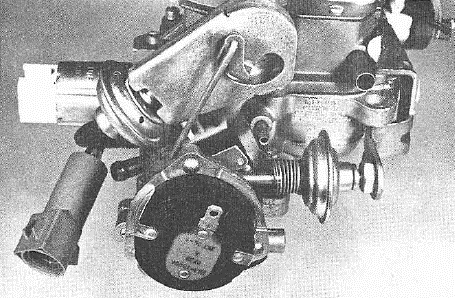
To meet federal regulations on tamper-proofing, some late models use rivets or breakaway screws to attach the thermostatic choke coil and housing. If you need to replace the thermostat, drill out the rivets and replace them with self-tapping screws.
For a period of time, regulations required tamper-proofing the choke pull-off linkage. On these units the choke pull-off. is spot welded to housing which serves as the mounting bracket and also a part of the tamperproof enclosure?
The outside cover plate is riveted on to enclose the choke pull-off link.
Part 3
Fast Idle and Unloader
During the warm-up period, it is necessary to provide a fast idle speed to prevent engine stalling. This is accomplished by a fast idle cam connected to the choke shaft. The choke trip lever contacts the fast idle cam. The fast idle link attached to the throttle lever contacts the choke trip lever and prevents the throttle valve from returning to a normal warm engine idle position while the automatic choke is in operation.
If during the starting period the engine becomes flooded, the choke valve may be opened manually to clean out any excess fuel in the intake manifold. This may be accomplished by depressing the accelerator pedal to the floor mat and engaging the starter. The unloader projection on the fast idle link will contact the unloader lug on the choke trip lever and in turn partially open the choke valve.
EGR Control
All vehicles since 1973 have used an EGR, or “Exhaust Gas Recirculation,” system to lower emissions of nitrogen oxides.
The EGR valve is controlled either by a port in the throttle body above the closed throttle valve or by venturi vacuum.
The ported EGR control takes advantage of the throttle valve position to open the EGR valve. At idle, the port is on the atmospheric side of the throttle valve keeping the EGR valve closed. As the throttle valves are opened, the port is exposed to the manifold vacuum which opens the EGR valve.
The ported EGR uses a notched throttle valve to reduce sensitivity for smoother EGR operation.
Some models use the venturi vacuum control system whereby a vacuum tap at the throat of the carburetor venturi is used to provide a control signal.
Wide Open Throttle Dump Valve
Some applications use a W.O.T., or “Wide Open Throttle,” dump valve for the EGR system. The dump valve will “kill” the venturi signal to the atmosphere. The dump valve is in series with the EGR venturi port in the carburetor and the amplifier. At wide-open throttle, the arm on the throttle shaft opens the dump valve cutting off the EGR and giving full horsepower.
Throttle Positioner Solenoid
In some applications, the BBD carburetor uses a throttle positioner solenoid as part of a catalyst protection system. The system’s function is to prevent unburned hydrocarbons from entering the atmosphere through the vehicle’s exhaust system when the engine is decelerated from a high RPM.
The solenoid works in conjunction with an electronic speed switch and positions the throttle valves during rapid deceleration to prevent over-rich mixtures contaminating the catalytic converter.
The electronic speed switch senses the pulses from the electronic ignition system. When the engine is operating above approximately 2,000 R.P.M., the electronic speed switch energizes the throttle positioner solenoid. On deceleration, the throttle positioner solenoid holds the throttle valves to approximately 1,800 R.P.M. When engine speed drops below 2,000 R.P.M., the throttle positioner solenoid is de-energized allowing the throttle valves to close. Thus, the converter is protected from overheating.
Some California units use a vacuum throttle positioner which consists of an electronic speed switch, an electrically controlled vacuum solenoid valve, and a vacuum activated positioner.
Its function and operation are the same as the solenoid type positioner above.
Dashpot
Some applications use a slow closing throttle device commonly called a dashpot. They are used to delay or slow the throttle closing the last few degrees to prevent engine stalling at the lower speeds and also to eliminate a sudden peak of hydrocarbon emissions on sudden deceleration. At idle, the manifold pressure is very low and results in good vaporization of the air-fuel mixture in the intake manifold.
When the throttle valve is opened, manifold pressure increases. This increase in pressure in creases the boiling point of the liquid and prevents 100% vaporization of the air-fuel mixture. During these periods of high manifold pressures, there are some wet particles of fuel clinging to the inside of the intake manifold which is known as “wet manifold.”
During sudden deceleration, the manifold pressure goes back to a low-pressure state, the wet particles clinging to the inside of the intake manifold go back to a vapor state and are taken into the engine as a rich mixture. This is known as “manifold flash” and can cause the engine to die out, especially at low speeds. The dashpot slows the closing of the throttle the last few degrees to give the engine time to clear itself of manifold flash.
Purge Port
Starting in 1971 all outside carburetor vents had to be routed to a canister to prevent evaporative emissions to the atmosphere. A purge port has been added to the carburetor to purge the canister of these fuel vapors. The purge port is located above the throttle valve. As the throttle valves open, the purge port is exposed to low pressure which gives a predetermined airflow to scavenge these vapors from the canister.
Port relation is the position of the throttle valve relative to the idle port. Anything that changes this relationship will seriously affect idle, acceleration, E.G.R., spark and purge timing. Proper idle adjustment for correct positioning of the throttle valves is most important.
Transducer and Ground Switch
Carburetors used on the lean-burn engines use a throttle position transducer and a ground switch. The transducer is simply a device that changes mechanical motion to an electrical signal. It consists of a coil enclosed in plastic with a moveable iron core which is attached by linkage to the throttle lever. Its movement and position are always relative to throttle position and throttle movement. The transducer signals the E.S.A., or “Electronic Spark Advance,” computer the position and rate of change of the throttle. The E.S.A. then adjusts ignition timing to coincide with throttle position and rate of opening.
The function of the ground switch is to signal the E.S.A. computer when the throttle valves are closed. The E.S.A. retards timing at closed throttle position.
Some models incorporate a grounding switch to control the distributor solenoid. When the throttle valves are at idle position, the grounding switch grounds the distributor solenoid which retards ignition timing.
The O2 Feedback System Using Variable Air Bleeds
Carburetor Operation
The basic carburetor contains two fuel supply subsystems, the high-speed system, and the low-speed system. The high-speed system meters fuel with a tapered metering rod positioned in the jet by the throttle. Fuel is metered into the main nozzle well, where air from the feedback-controlled variable air bleed is introduced. Since this air is delivered above the fuel level, it reduces the vacuum signal on the fuel, consequently reducing the amount of fuel delivered from the nozzle.
The idle system is needed at low air flows through the venturi because there is an insufficient vacuum at the nozzle to draw fuel into the air stream. After leaving the main jet, fuel is supplied to the idle system by the low-speed jet. It is then mixed with air from the idle by-pass, then accelerated through the economizer and mixed with additional air from the idle bleed before being discharged from the idle ports below the throttle. Air from the variable air bleed is introduced between the economizer and idle bleed. This air reduces the vacuum signal on the low-speed jet and consequently the amount of fuel delivered to the idle system.
The variable air bleeds change the pressure difference which controls fuel flow thru the jets.
Two types of air metering control are used on the BBD O2 feedback system. The stepper motor with air metering pins is used on some applications, while others use a pulsed solenoid.
BBD With Stepper Motor
The variable air bleeds consist of tapered metering pins positioned in orifices by the stepper motor. This drive mechanism moves the pins in defined steps in response to signals from the oxygen sensor located in the exhaust and processed by the electronic control unit. The stepper motor moves the pins until the exhaust sensor indicates that the desired air-fuel ratio has been reached. Thus the pin movement adjusts the air-fuel ratio to compensate for changes detected in the exhaust gases.
Stepper Motor & Air Metering Pins
The digital linear actuator or stepper motor moves the metering pins, .400 inches from full lean to full rich. Full movement requires 100 steps at .004 inches per step.
Fast speed is 100 steps per second, slow speed is 12 steps per second.
During the initial power-up of the stepper motor, the metering pins must be sent to an end stop to give the electronic control unit a stable reference. The metering pins must then be backed off to the desired position.
This initialization of the metering pins occurs in open-loop mode. When the ignition is turned on, and again when the starter is engaged, the metering pins move inward (rich position) 127 steps and outward (lean position) 35 steps. This locates the pins near the position to give the average air-fuel ratio for complete fuel combustion (stoichiometric ratio).
Coil Windings
The stepper motor incorporates a unipolar winding which has 2 coils wound on the same bobbin, per stator half, for a total of 4 coils.
A threaded shaft provides linear movement which is bidirectional. Movement and direction is controlled by motor phasing sequence.
Checking Stepper Motor
To check stepper operation, remove the air cleaner from the carburetor. The air metering pin for the high-speed circuit is visible looking into the air horn of the carburetor.
Turning the ignition switch on should cause the initialization of the air metering pins. If no movement is observed, check electrical connections and windings.
Checking Coils
Check each winding of the stepper motor by disconnecting the wiring harness from the stepper motor. With an ohmmeter, check each coil by connecting to the “C” terminal and to the ground terminal of each coil. There should be 78 ohms, plus or minus 25 ohms at room temperature.
Movement of the air metering pins can be accomplished by applying 12 volts to the “C” terminal and grounding the coils as per the phasing sequence.
Air Management Switch
On some applications with an O2 feedback system, a microswitch is incorporated which is operated by the throttle shaft. It is part of the air management system and makes contact at 25 degrees before wide-open throttle. When contact is made, it dumps the air pump air to the atmosphere.
Some models use a pulsed solenoid to control the variable air bleeds. This eliminates the metering pins, as the pulse cycle controls the air-fuel ratio.
The solenoid has only two positions of operation, opened when energized to bleed air to both the high speed and low-speed circuits, or closed when deenergized, cutting off the air bleeds.
Pulse Width ModulationDuring normal operation, the solenoid goes through one open and one closed period in each cycle. The pulse solenoid is 10 Hz. frequency (10 cycles per second) which adds up to 100 Mil per second per cycle.
Each cycle has a particular time period, ‘T’, from the beginning of one cycle to the next and is held constant during operation (always 10 cycles per second).
During any one cycle, the solenoid is open for some fractional period of time, “t”. The duration of “t” can be varied, thus varying the duty cycle and amount of air bleed to the carburetor circuits.
100% duty cycle means full air bleed for approximately 100 Mil per second per cycle. This duty cycle may be varied from zero percent to one hundred percent.
Pulse width modulation of the airflow is controlled by the solenoid duty cycle as signaled by the computer.
Specification: Resistance 22 plus or minus 1 ohm at room temperature
Checking Pulse Solenoid
Checking the pulse solenoid is very quick and easy. With the engine at operating temperature, merely place a hand on the solenoid. if not pulsing, shut off the engine and disconnect pulse solenoid wires.
Check for open or shorted coil winding by using an ohmmeter across the two blue wires. (The coil is not grounded to the case). Should be 22 ohms resistance at room temperature.
If winding is working properly, momentarily flash 12 volts to pulse solenoid to check armature movement.
A dwell meter can be used with the pulse solenoid to give an overall indication of the operation. The dwell reading would be indicative of the ratio of “on” to “off” time which is referred to as pulse width modulation. With the engine warmed up, place fast idle cam to obtain approximately 1200 R.P.M. and check to dwell reading. Closing the choke valve slightly to richen the air-fuel mixture should give an increase in dwell.
A command from the computer to “lean out” would give a dwell reading between 30 to 60 degrees dwell, a rich command would read between 0 to 30 degrees dwell. An ideal reading would be between 28 to 32 degrees.
The dwell meter should always be set on the 6-cylinder scale.
