
WHAT IS A CARBURETOR?

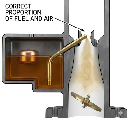



A carburetor is a metering device which mixes fuel with air in the correct proportions and delivers them to the engine cylinders as a combustible mixture.
The automobile engine's source of fuel for power is gasoline. In liquid form, however, the gasoline is of little use; its energy can be released by combustion, only when combined properly with the correct amount of air and delivered to the cylinder of the engine as a combustible mixture.
PURPOSE OF A CARBURETOR
The purpose of a carburetor on a gasoline engine is a meter, atomize, and distribute the fuel through-out the air flowing into the engine. All of these functions are designed into the carburetor and are carried out by the carburetor automatically over a wide range of engine operating conditions, such as varying engine speeds, load, and operating temperature.
The carburetor also regulates the amount of air/fuel mixture which flows to the engine. It is this mixture flow regulation which gives the driver control of the engine speed.
Regardless of engine RPM or load the engine encounters, the carburetor must automatically perform its three basic functions.
The automotive carburetor is a very intricate device; however, when studied one phase at a time, the functions of the carburetor are easily understood.
As mentioned above, the three main functions of the carburetor are to meter, atomize, and distribute the fuel.
METERING
Good combustion demands a correct mixture ratio between fuel and air, commonly called the air/fuel ratio. Too much fuel results in a "rich" mixture, while too little fuel results in a "lean" mixture. To release all possible energy by combustion, the right amount of fuel must be mixed with a given amount of air. The metering job of the carburetor is to furnish the proper air/fuel ratio for all conditions, so that the engine operation will neither be too lean for power requirements or too rich for economy.
ATOMIZATION
Atomization means breaking the liquid fuel into very small particles so that it can readily vaporize and mix with air. With the fuel broken into small particles, there is more air contact. The more air contact - the better the vaporization.
Atomization is accomplished in two ways:
- (A) above shows air being bled intot he fule as it moves through the carburetor passages. This causes a turbulence which breaks the solid stream into smaller particles
- The main fuel nozzle (B) is located at the point of highest air velocity, (lowest pressure) so that the air actually tears the fuel into fine spray as it enters the air steam.
DISTRIBUTION
For good combustion and smooth engine operation, the air and fuel must be thoroughly and uniformly mixed, delivered in equal quantities to each cylinder and evenly distributed within the combustion chamber.
Good distribution requires good vaporization. A gaseous mixture will travel much more easily around corners in the manifold and engine, while liquid particles, being relatively heavy, will try to continue in one direction and will hit the walls of the manifold or travel on to another cylinder.
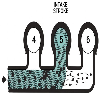
As an example, consider a six cylinder engine with the carburetor mounted at the center of the manifold. The mixture for cylinders 4, 5, and 6 will initially travel towards the rear of the engine.
If #5 is on the intake stroke, the mixture will be drawn sharply around the corner to #5 at right angles to the original direction. The large drops of gasoline won't make such a sharp turn and will continue in their path to the rear of the manifold, where they will probably be drawn into #6 on its intake stroke. Thus, #5 receives a leaner mixture and #6 receives a richer mixture than originally entered the manifold.
To compensate for these problems, manifold are tailored to the engines to minimize the sharp corners and provide as smooth a flow as possible. The carburetor's principle job in distribution is to break up the fuel as finely as possible and furnish a uniformly vaporized mixture to the manifold.
PRICIPLES OF OPERATION
VACUUM
Carburetors of all types operate on the basic principle of pressure difference.
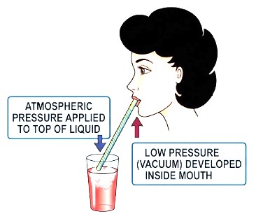
Any pressure less than atmospheric is considered a vacuum or a low pressure area. When a straw is sucked on to obtain liquor from a container, a vacuum is produced in the mouth. Atmospheric pressure on the liquid in the container is greater than that on the discharge end of the straw. The greater pressure on the liquid will force the liquid into the low pressure area which, in this case, is the mouth. In the engine, as the piston moves downward on the intake stroke, with the intake valve open, a partial vacuum is created. As the piston moves further downward in the cylinder, there is increased suction or increased vacuum but decreased pressure.
Engine intake manifold vacuum is normally measured by a vacuum gauge which is calibrated in inches of mercury. The higher the vacuum reading, the less air pressure inside the intake manifold. Therefore, there will be more pressure difference between air inside the intake manifold and the outside atmosphere. This pressure difference is the force which causes fuel and air to flow through the carburetor unit. Fuel and air always move from high to low pressure areas.
VENTURI PRINCPLE
To obtain greater pressure drop at the tip of the nozzle to make the fuel flow, the principle of increasing the air velocity to create a low pressure area is used. A device called a venturi increases the air velocity and lowers the pressure at the nozzle.
The venturi is a specially designed restriction which causes air to momentarily increase its speed while passing through it. This creates a drop in air pressure, commonly called vacuum, in the venturi. As the speed of the air flow in the carburetor increases with an increase in engine speed, the vacuum in the venturi becomes correspondingly greater. Most carburetors use a primary venturi and one or more boost venturi. The boost venturi is located over the primary venturi with its discharge end in the low pressure area of the primary venturi. The purpose of the boost venturi is to further lower the pressure at the nozzle. Additional boost venturi may be used for finer control of the pressure drop; however, at high speeds they tend to restrict the air flow to the engine.
BASIC CARBURETOR SYSTEMS
For demonstration purposes, illustrations show a Rochester carburetor which include six basic systems: float, idle, main metering, power, accelerator pump, and choke. The following explanation shows basically how each system operates to provide efficient carburetion for all operating conditions.
FLOAT SYSTEM
Fuel in the carburetor float bowl must be maintained at a specified level for correct fuel metering under all driving conditions. The float system accomplishes this by using a float, which exerts force against a needle valve to shut off fuel flow into the bowl when the specified level is reached.
Fuel from the fuel pump enters through the fuel inlet and into the float bowl through the orifice in the fuel valve (needle seat). As the level in the bowl rises, the buoyant action of the float raises the float which, in turn, seats the needle valve in the seat. When fuel is being used from the bowl, the float drops enough to allow the needle to be unseated and fuel will enter past the needle to maintain the level in the float bowl.
The liquid level controlled by the float setting is an important part of the calibration of the carburetor. If the liquid level is lower than specified, greater than normal air flow will be required through the venturi to lift a given amount of fuel from the float bowl, so the mixture will be lean.
The effects of a lowered liquid level causes poor performance in the main metering system and a definite loss of power. High liquid level can result in premature main metering delivering and fuel spillage during normal car maneuvering, each of which causes excess fuel consumption and an over-rich condition.
The float system is perhaps one of the most important systems in the carburetor, as the correct operation of all other systems depends on a fixed level of fuel in the float bowl.
IDLE SYSTEM
During engine idle operation, air flow through the carburetor venturi is very low and is not great enough to meter fuel properly from the main discharge nozzle. Therefore, the idle system is used to provide the proper mixture ratios required during engine idling and low speed operation.
The idle system consists of an idle tube, idle passages, idle air bleeds, off-idle discharge ports, idle mixture adjusting needle and the idle mixture needle discharge port.
In the idle speed position, the throttle valve is slightly open, allowing a small amount of air to pass between the wall of the carburetor bore and the edge of the throttle valve. Since there is not enough air flow for venturi action, the fuel is made to flow by the application of vacuum directly through the idle system to the fuel in the carburetor bowl.
The low pressure below the throttle valve (manifold vacuum) will cause the fuel to flow through the idle tube, into the idle passage, where it is mixed with air from the air bleed. This is the first stage of atomizing the fuel. The mixture continues down the passage, past the off idle ports. At this point these ports act as air bleeds to further break up the mixture. The mixture flows past the mixture screw into the carburetor bore and into the engine intake manifold. The mixture screw controls the idle mixture and is turned in to lean the idle mixture and backed out to richen it.
As the throttle valve is opened, during slow speed or off-idle operation, the off-idle ports are exposed to manifold vacuum. At this time they begin feeding extra fuel mixture for off-idle requirements. Thus, the off-idle ports have a dual purpose. At idle they act as air bleeds but during the off-idle range they change to fuel mixture feeds.
MAIN METERING SYSTEM
The main metering system controls the economy range of the carburetor. It consists of a main jet and a main nozzle with air bleeds in it. The main jet is a very accurately machined orifice, which controls the fuel flow through the main well in which the main nozzle is located. An air bleed in the main well and the air bleeds in the main nozzle keep the mixture constant throughout the operating range of the main metering system for maximum economy.
The main metering system operates as follows:
As the throttle valve is opened, air velocity through the venturi system increases which in turn greatly decreases the pressure in the venturi and the main fuel nozzle. This will cause the fuel to be pushed through the main metering jet and up the main nozzle. As the solid fuel enters the nozzle, it is mixed with air through the calibrated holes in the nozzle. This air aids in atomizing the air/fuel mixture for improved distribution. The mixture continues through the passage and enters the air stream at the boost venturi. At this point it is mixed with the incoming air and is carried past the throttle valve and into the manifold, for distribution to the engine cylinders.
POWER SYSTEM
As explained previously, maximum engine power requires the use of all available air for combustion; to accomplish this a slightly richer fuel mixture is needed. To supply the additional fuel, the power system is used to supplement the main metering system.
The power system consists of a spring loaded power piston, a vacuum passage to the intake manifold, a power valve, and a power restriction between the power valve and the main well. The power piston determines when the power valve opens, and the power restriction determines how much fuel will be added to the main well in addition to what the main jet is already supplying.
The power system, controlled by manifold vacuum, provides an additional fuel inlet to the main nozzle under low vacuum conditions. Normally, the power piston is held up by hihg manifold vacuum but, any time manifold vacuum falls below the tension of the piston spring, the spring tension forces the piston down, opening the power valve to increase the fuel flow to the main nozzle. This system is operative only when the engine demands enrichment for extra power. This usually occurs at approximately 9" of manifold vacuum.
PUMP SYSTEM
When the throttle is opened rapidly, the air flow and manifold vacuum change almost instantly. Because of the great difference in weight between air and fuel, any sudden change in throttle opening results in an immediate increase in air intake but the fuel, having greater weight tends to lag behind. THe result of this is momentary leanness. The accelerator pump provides the extra fuel necessary to overcome this leanness and give smooth operation on all throttle openings. This is accomplished by discharging extra fuel into the venturi air stream whenever the throttle valve is opened.
The pump system utilizes a pump plunger that is linked to the throttle lever by mechanical linkage. Any opening of the throttle valve causes the pump plunger to move downwards in the pump well. This action forces fuel through the pump passages and out the pump jets into the incoming air stream. As the throttle is closed, the pump plunger is lifted up in the well, creating a low pressure below the plunger. An inlet ball check is lifted off its seat and allows fuel to flow into the pump well. At the same time, the discharge ball check seats to prevent air from leaking into the discharge passage. The delayer spring and return spring work together to give a controlled, smooth discharge for a moment after the accelerator pedal stops moving.
CHOKE SYSTEM
The purpose of the choke system is to provide a richer mixture for cold engine starting and operation. Mixture enrichment is necessary because fuel vapor has a tendency to condense on cold engine parts, such as the inside area of the intake manifold and cylinder head, thereby, decreasing the amount of combustible mixture available in the engine cylinder.
In the automatic choke carburetor, when the engine is cold, a thermostatic coil holds the choke valve closed. This cuts down the air supply and raises the vacuum applied to the fuel outlets, so that more than the usual fuel may be drawn into the cold engine.
As the engine warms up, the manifold vacuum supplied to the choke housing pulls hot air from the choke stove through a passage in the choke housing to heat the thermostatic coil. The thermostatic coil relaxes gradually until the choke valve is fully opened. The choke piston is used as an aid to off-set tension of the thermostatic coil and in choke valve opening.
VACUUM SPARK ADVANCE
Along with the mechanical spark advance, another method is used to advance ignition spark under load. This is commonly called the vacuum operated spark advance unit. The vacuum advance unit supplements the mechanical advane, however, it operates differently as it varies spark timing in relation to engine load. Engine load can best be determined by manifold vacuum so consequently, the vacuum advance unit mounted on the distributor is connected directly to engine intake manifold vacuum.
Although spark timing is not a direct function of the carbureto, it is used on some applications to control the vacuum operated advance unit on the distributor during the idle and off-idle range. On these units a calibrated port is located in the throttle bore just above the throttle valves. It is connected by a vacuum line directly to the distributor vacuum advance unit.
In the curb idle position the throttle valve is below the spark port so consequently, no vacuum is applied to the advance unit and the spark advance remains in the retarded position. As the throttle valve is opened and engine speed increases the throttle valve moves past the spark port so that manifold vacuum below the throttle valve is applied directly to the vacuum advance unit. Timed spark advance is used on applications where engine design demands retarded spark for a smooth idle and performance improvements at low speeds.
On other units the vacuum advance line may be connected directly to the manifold or carburetor bore below the throttle valve. In this case the engine will idle with full spark advance. The full advance spark at idle is used on engine applications where it is not detrimental to engine idle, and improves engine cooling. When setting ignition timing, the vacuum advance line should always be removed, especially on engine using full spark advance at idle as initial ignition timing will be set retarded if this is not done. The end result will be very poor fuel economy. To be sure, always disconnect the vacuum advance line to the manifold or carburetor when setting initial engine spark timing.
